Titanium powder sintered compact

a titanium powder and compact technology, applied in metal-working apparatus, electrical equipment, fuel cell details, etc., can solve the problems of poor reverse-washing reproducibility, difficult to mold titanium powder into cylinders with a large height, poor bendability of titanium powder sintered compact, etc., to achieve high corrosion resistance, small thickness, and large area

Inactive Publication Date: 2007-11-20
OSAKA TITANIUM TECHNOLOGIES
View PDF8 Cites 16 Cited by
  • Summary
  • Abstract
  • Description
  • Claims
  • Application Information

AI Technical Summary

Benefits of technology

[0041]In order to solve these problems, the present inventors focused attention on spherical gas atomized titanium powder. Spherical gas atomized titanium powder is powder of titanium or a titanium alloy produced by means of a gas atomization method and individual particles are of a sphere with a smooth surface since the individual particles are formed by solidification during the time when melt spray of titanium or a titanium alloy is flying. Furthermore, particle diameters can be very much reduced down to as small as 100 μm or less on average and screening is easily applied for classification by particle diameter.
[0084]A highly corrosion resistant porous plate of the present invention is especially preferable as an ink dispersion plate for an ink jet printer small in thickness and large in area, requiring a uniform void ratio and a high corrosion resistance, and greatly contributes to reduction in fabrication cost for the dispersion plate.

Problems solved by technology

Such a titanium powder sintered compact is, however, very poor in bendability as described above.
It is difficult to mold the powder into a cylinder with a large height, however, and reverse-washing reproducibility is also poor when the titanium sintered compact is used as a filter.
Even with press molding applied, uniformity of a cavity diameter is still insufficient and a skin layer receiving no press molding is conspicuously non-uniform in cavity diameter as described above.

Method used


Image

  • Titanium powder sintered compact
  • Titanium powder sintered compact
  • Titanium powder sintered compact

Examples


example 1

[0105]Billets were obtained from raw material titanium sponge and a melt thereof produced by electromagnetic induction heating was gas atomized in an Ar gas atmosphere. Obtained titanium powder was classified by vibration screening to obtain spherical powder with an average particle diameter of 10 μm. A high density alumina vessel in the shape of a square having one inner side of 100 mm and a depth of 3 mm was filled with the powder without applying a pressure thereto and then the powder was sintered keeping it at a vacuum degree of 7×10⁻³ Pa at 1000° C. for 15 minutes without applying pressure to the powder.

example 2

[0106]A titanium sintered filter was fabricated in the same method and conditions as in Example 1 with the exception that the gas atomized powder was classified by vibration screening to obtain spherical powder with an average particle diameter of 29 μm.

example 3

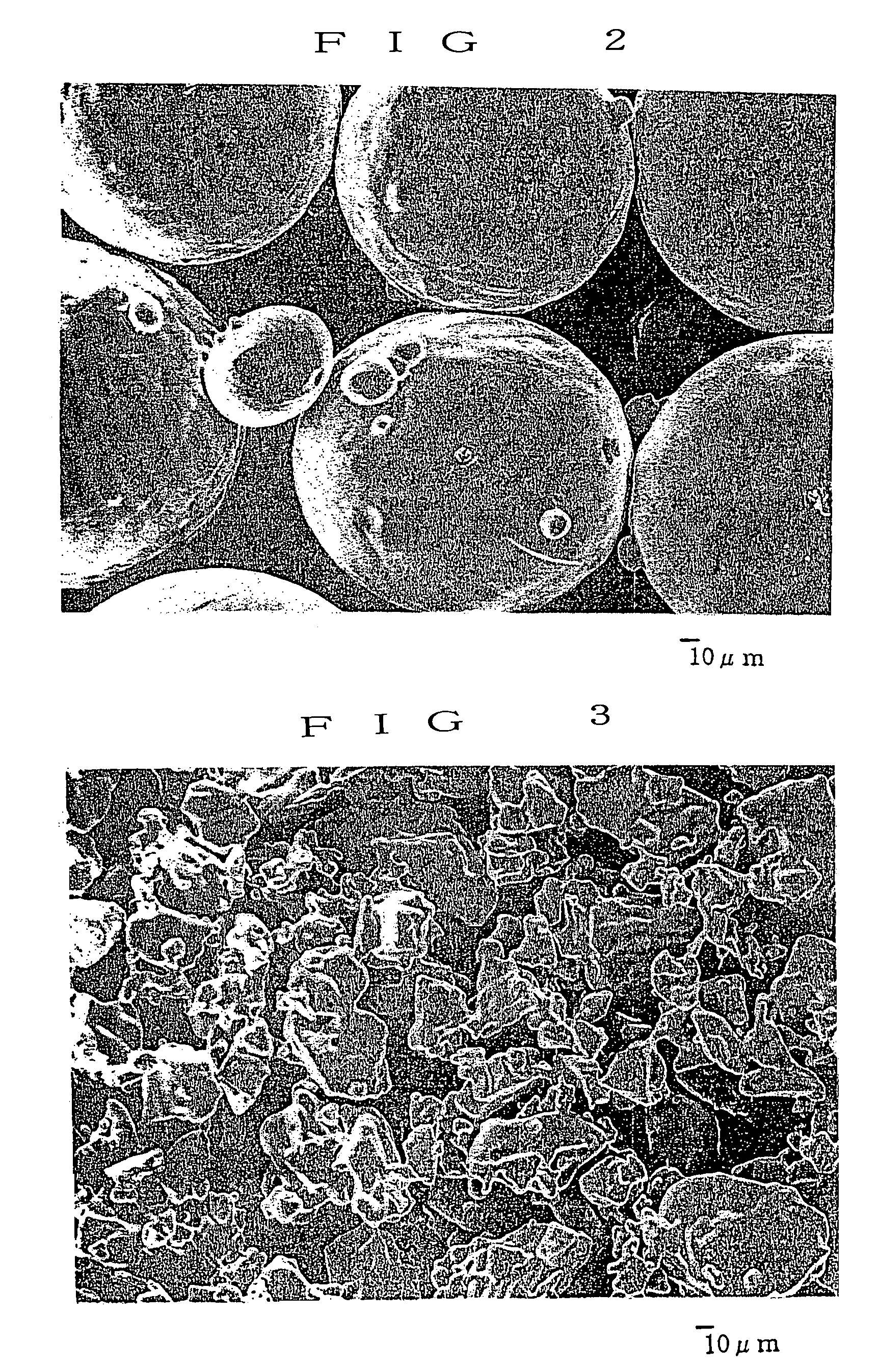
[0107]A titanium sintered filter was fabricated in the same method and conditions as in Example 1 with the exception that the gas atomized powder was classified by vibration screening to obtain spherical powder with an average particle diameter of 124 μm. In FIG. 2, there is shown an electron microscopic photograph of the titanium sintered filter. It is found that each of particles of the titanium sintered filter is maintained in the shape of an unchanged sphere with many of voids.


PUM

PropertyMeasurementUnit
diameteraaaaaaaaaa
diameteraaaaaaaaaa
pore diameteraaaaaaaaaa

Abstract

Provided are a porous sintered compact suitable for a filter, a power feeder in a polymer electrolyte membrane type water electrolyzer, a current collector in a solid polymer fuel cell and in addition a liquid dispersion plate, especially an ink dispersion plate for an ink jet printer ink and the like. A titanium powder sintered compact made of a plate-like porous compact is obtained by sintering spherical powder made of titanium or a titanium alloy produced by means of a gas atomization method. A void ratio in the range of from 35 to 55% is realized by filling without applying a pressure and sintering without applying a pressure.

Description

CROSS-REFERENCE TO RELATED APPLICATION[0001]This application is a continuation application of U.S. Ser. No. 10 / 468,058, filed Feb. 2, 2004, now abandoned, which is a 371 of PCT / JP02 / 01332, filed Feb. 15, 2002 the entirety of which are incorporated herein.TECHNICAL FIELD[0002]The present invention relates to a porous titanium powder sintered compact employed as a filter, a power feeder in a polymer electrolyte membrane type water electrolyzer, a current collector in a solid polymer fuel cell and in addition a liquid dispersion plate, especially an ink dispersion plate for an ink jet printer and the like.BACKGROUND ART[0003]A metal powder sintered compact has been adopted as one of filters employed in the chemical industry, the polymer industry, the chemicals industry and others. As metals herein, there have been used generally brass, stainless steel and, recently, titanium.[0004]Titanium is greatly excellent in corrosion resistance, acid proofness and the like as compared with stainl...

Claims


Application Information

Patent Timeline
Patent Type & Authority Patents(United States)
IPC IPC(8): B01D24/00C22C1/04H01M4/00B22F3/00B22F1/065B01D39/20B22F3/11B22F5/00H01M8/02H01M50/571
CPCB01D39/2034B22F1/0048B22F3/11B22F3/1103B22F3/1109H01M8/0232H01M8/0247B01D39/2079B22F3/004B22F3/10Y10T428/12021B01D2201/188B22F2998/00B22F2998/10B22F2999/00Y02E60/50Y10T428/12014B22F9/082B22F2207/11B22F3/02B22F1/065C25B11/031C25B11/037C25B11/042
Inventor ONISHI, TAKASHIOGASAWARA, TADASHIWATANABE, MUNETOSHIKATO, MASAMICHI
Owner OSAKA TITANIUM TECHNOLOGIES
Why Eureka
Try Eureka