Switching power supply circuit

a power supply circuit and power supply technology, applied in the direction of electric variable regulation, process and machine control, instruments, etc., can solve the problems of increased part cost, and limited enhancement of power conversion efficiency of switching converters, so as to achieve the effect of enhancing ac-dc power conversion efficiency

Inactive Publication Date: 2007-11-20
SONY CORP
View PDF10 Cites 6 Cited by
  • Summary
  • Abstract
  • Description
  • Claims
  • Application Information

AI Technical Summary

Benefits of technology

[0096]According to the configuration described above, the switching power supply circuit of the present invention has a basic configuration as a composite resonance type converter wherein a current resonance type switching converter and a primary side partial voltage resonance circuit are combined on the primary side. In addition, a gap of a predetermined length or more is formed in the core of the converter transformer such that the primary winding and the secondary winding have a loose coupling state with a coupling coefficient equal to or lower than a required value. Further, the numbers of turns of the primary winding and the secondary winding are selected such that the induced voltage per one turn of the secondary winding is set to a voltage with which secondary side current to flow through the secondary side of the converter transformer exhibits a continuous operation mode. Consequently, since the primary side series resonance current to flow through the primary winding can be reduced together with a decrease of the load power, reduction of the power loss on the primary side can be achieved and enhancement of the AC-DC power conversion efficiency can be achieved.
[0103]By a partial voltage resonance action of the partial voltage resonance circuit, also the waveform of the primary side series resonance current to flow through the primary side series resonance capacitor C1 can be made an M-shaped waveform, and the current waveform of the current flowing through the switching element can be made an M-shaped waveform. Consequently, the peak level of the primary side series resonance current to flow through the primary side or the current to flow through the switching element where the load power is within a range from 200 W to 0 W can be lowered, and enhancement of the AC-DC power conversion efficiency can be achieved.

Problems solved by technology

Further, it is known that the switching converters are limited in enhancement in the power conversion efficiency from their operation characteristics.
Incidentally, with a power supply circuit constructed as a current resonance type converter of the half bridge type so as to obtain a DC input voltage by means of a full-wave rectification circuit, there is a limitation to enhancement of the power conversion efficiency.
However, in this instance, it is necessary to incorporate two smoothing capacitors in the voltage doubler rectification circuit, and the part cost becomes higher as the voltage withstanding property of the switching elements Q1 and Q2 and the resonance capacitors increases.
Further, as a problem common to the related art power supply circuits described above, particularly the power conversion efficiency drops as the load power decreases.

Method used


Image

  • Switching power supply circuit
  • Switching power supply circuit
  • Switching power supply circuit

Examples


first embodiment

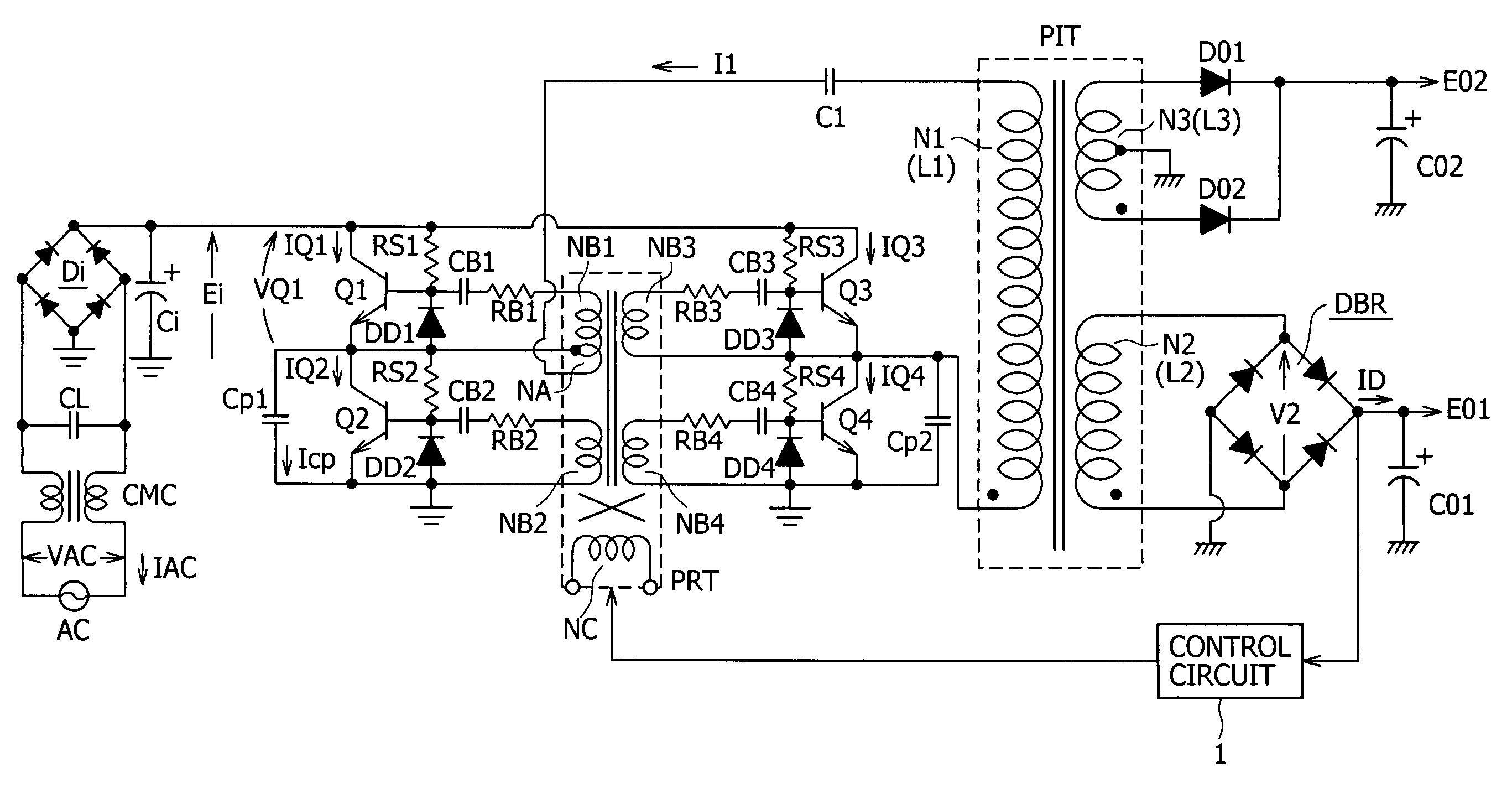
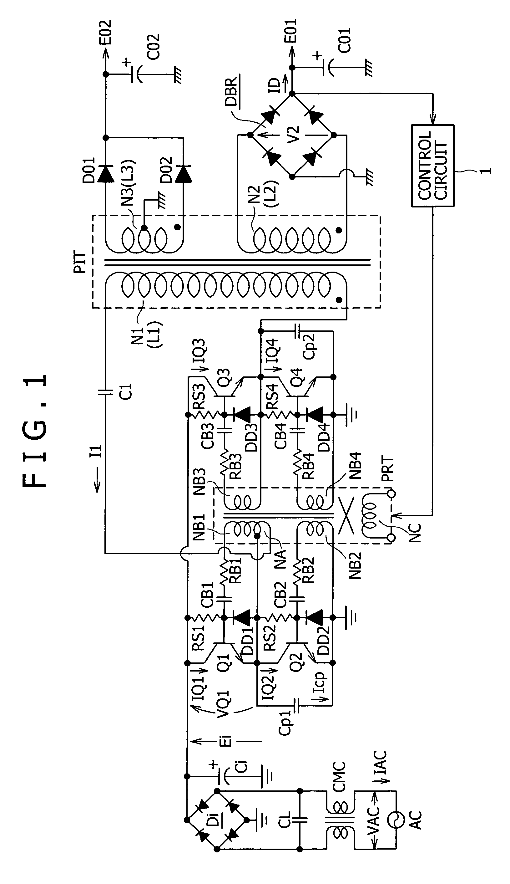
[0134]FIG. 1 shows an example of a configuration of a switching power supply circuit as the present invention.

[0135]The power supply circuit shown in FIG. 1 is a switching power supply circuit as a composite resonance type converter which includes, on the primary side, a self-oscillation current resonance type converter of a four-element configuration and a primary side partial voltage resonance circuit including a primary side partial voltage resonance capacitor.

[0136]In the present power supply circuit, a common mode choke coil CMC and a cross capacitor CL are provided as a noise filter for removing common mode noise from an commercial AC power supply AC and form a so-called line filter.

[0137]Further, as a rectification circuit system for producing a DC input voltage from a commercial AC power supply, a full-wave rectification smoothing circuit formed from a bridge rectification circuit Di and a smoothing capacitor Ci is provided and produces a rectified smoothed voltage Ei corres...

second embodiment

[0201]FIG. 5 shows an example of a configuration of a switching power supply circuit as the present invention. It is to be noted that like elements to those of FIG. 1 are denoted by like reference characters and description thereof omitted herein.

[0202]The power supply circuit shown in this figure includes a combination of a partial voltage resonance circuit with a separately excited current resonance type converter. Further, the power supply circuit adopts a configuration ready for the condition of the commercial AC power supply AC=100 V system.

[0203]In the power supply circuit shown in this figure, a full-wave rectification circuit formed from a bridge rectification circuit Di and a single smoothing capacitor Ci is provided for a commercial AC power supply AC. A rectified smoothed voltage Ei (DC input voltage) is obtained across the smoothing capacitor Ci by full-wave rectification operation of the bridge rectification circuit Di and the smoothing capacitor Ci. The rectified smoot...

third embodiment

[0245]FIG. 10 shows an example of a configuration of a switching power supply circuit as the present invention. It is to be noted that, in FIG. 10, like elements to those of FIGS. 1 and 5 are denoted by like reference characters, and description of them is omitted herein.

[0246]First, the power supply circuit shown in FIG. 10 has a self-excitation configuration as a current resonance type converter wherein two switching elements are connected in a half-bridge connection.

[0247]Further, in the power supply circuit shown in FIG. 10, a voltage doubler rectification circuit formed from two rectification diodes D1 and D2 of the low speed recovery type and two smoothing capacitors Ci1 and Ci2 connected in such a manner as seen in the figure is provided as a rectification circuit system for producing a DC input voltage (rectified smoothed voltage Ei) from a commercial AC power supply (AC input voltage VAC). In the present voltage doubler rectification circuit, a rectified smoothed voltage Ei...


PUM

PropertyMeasurementUnit
withstanding voltageaaaaaaaaaa
power conversion efficiencyaaaaaaaaaa
voltageaaaaaaaaaa

Abstract

A switching power supply circuit which can achieve enhancement of the power conversion efficiency is disclosed. In a composite resonance converter wherein a current resonance type converter constructed on the primary side and a primary side partial voltage resonance circuit are combined, a primary side DC input rectification circuit is formed from a full-wave rectification circuit. Further, a gap G of the core of an insulating converter transformer (PIT) is set to 2.0 mm to set the coupling coefficient of the primary winding (N1) and the secondary winding (N2) to approximately 0.81 of a loose coupling state. Further, the numbers of turns of the primary winding (N1) and the secondary winding (N2) are selected so that the induced voltage per one turn of the secondary winding (N2) is 2 V or less. With the configuration, if the leakage inductance (L1l) of the primary winding (N1) and the leakage inductance (L2l) of the secondary winding (N2) are increased, then reduction of the primary side current (I1) in a light load condition can be achieved and the switching output current (IQ1), (IQ2) can be reduced.

Description

TECHNICAL FIELD[0001]This invention relates to a switching power supply circuit provided as a power supply in various electronic apparatus.BACKGROUND ART[0002]Various switching power supply circuits are widely known including, for example, a switching power supply circuit of the flyback converter type or the forward converter type. The switching converters of the types mentioned are restricted in suppression of switching noise because the switching operation waveform is a rectangular waveform. Further, it is known that the switching converters are limited in enhancement in the power conversion efficiency from their operation characteristics.[0003]Therefore, various switching power supply circuits which rely upon various resonance type converters have been proposed by the applicant of the present application. According to the resonance type converters, a high power conversion efficiency can be obtained readily, and low noise is achieved because the switching operation waveform is a s...

Claims


Application Information

Patent Timeline
Patent Type & Authority Patents(United States)
IPC IPC(8): H02M3/335H01F17/00H02M3/28H02M3/338
CPCH02M3/3385Y02B70/1433H02M2001/009H02M1/009Y02B70/10H02M3/28
Inventor YASUMURA, MASAYUKI
Owner SONY CORP
Why Eureka
Try Eureka