Method and device for operating a gas turbine with a fossil-fuel fired combustion chamber

a technology of fossil fuel and combustion chamber, which is applied in the direction of steam engine plants, machines/engines, mechanical equipment, etc., can solve the problems of power stations that require substantial effort to handle and pollute the environment, and achieve the effect of reducing the risk of carbon dioxide escaping

Inactive Publication Date: 2007-11-27
SIEMENS AG
View PDF10 Cites 53 Cited by
  • Summary
  • Abstract
  • Description
  • Claims
  • Application Information

AI Technical Summary

Benefits of technology

[0018]The invention proceeds from the observation that a reduction in exhaust gas with a nitrogen oxide content can in particular be achieved by reducing the oxygen content of the air mixture which is used for combustion and which is channeled to the combustion chamber. There is a consequent drop in the partial oxygen pressure in the combustion flame which results in a required reduction in the rate at which nitrogen oxides form, and, owing to the high inert gas component in an air mixture of this type, the combustion flame has a lower temperature than when combustion takes place with normal combustion air, having an approximately 21% oxygen content, being supplied.
[0040]This minimizes both the risk of the carbon dioxide's escaping from the storage facility into the atmosphere and the safety requirements placed on the storage facility.

Problems solved by technology

The environment is also polluted with the above-mentioned climatically harmful gasses produced from generating electrical energy by the burning of fossil fuel.
However, even these power stations require substantial effort to handle the climatically harmful gases they produce in an environmentally friendly manner.
This necessities correspondingly large dimensioning of a carbon dioxide precipitation plant provided for this purpose and is associated with high energy requirements.

Method used


Image

  • Method and device for operating a gas turbine with a fossil-fuel fired combustion chamber
  • Method and device for operating a gas turbine with a fossil-fuel fired combustion chamber

Examples


Embodiment Construction

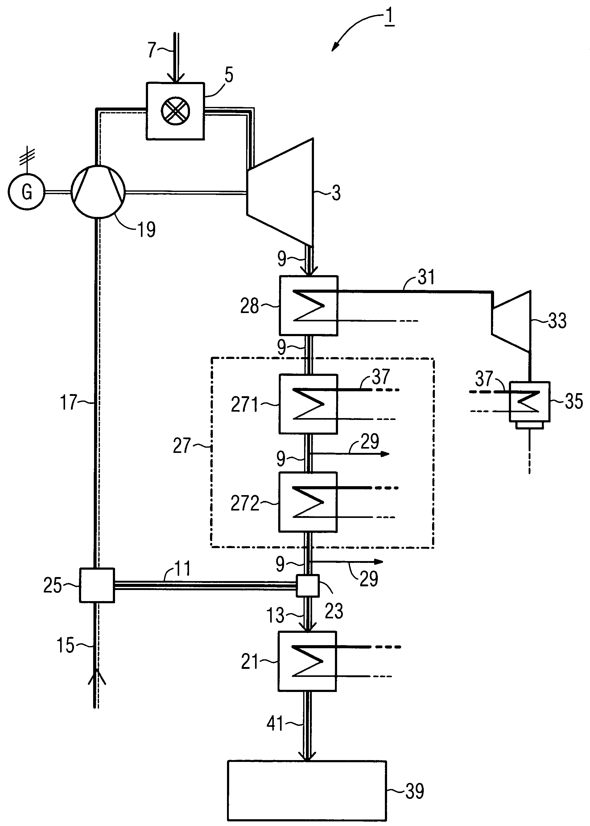
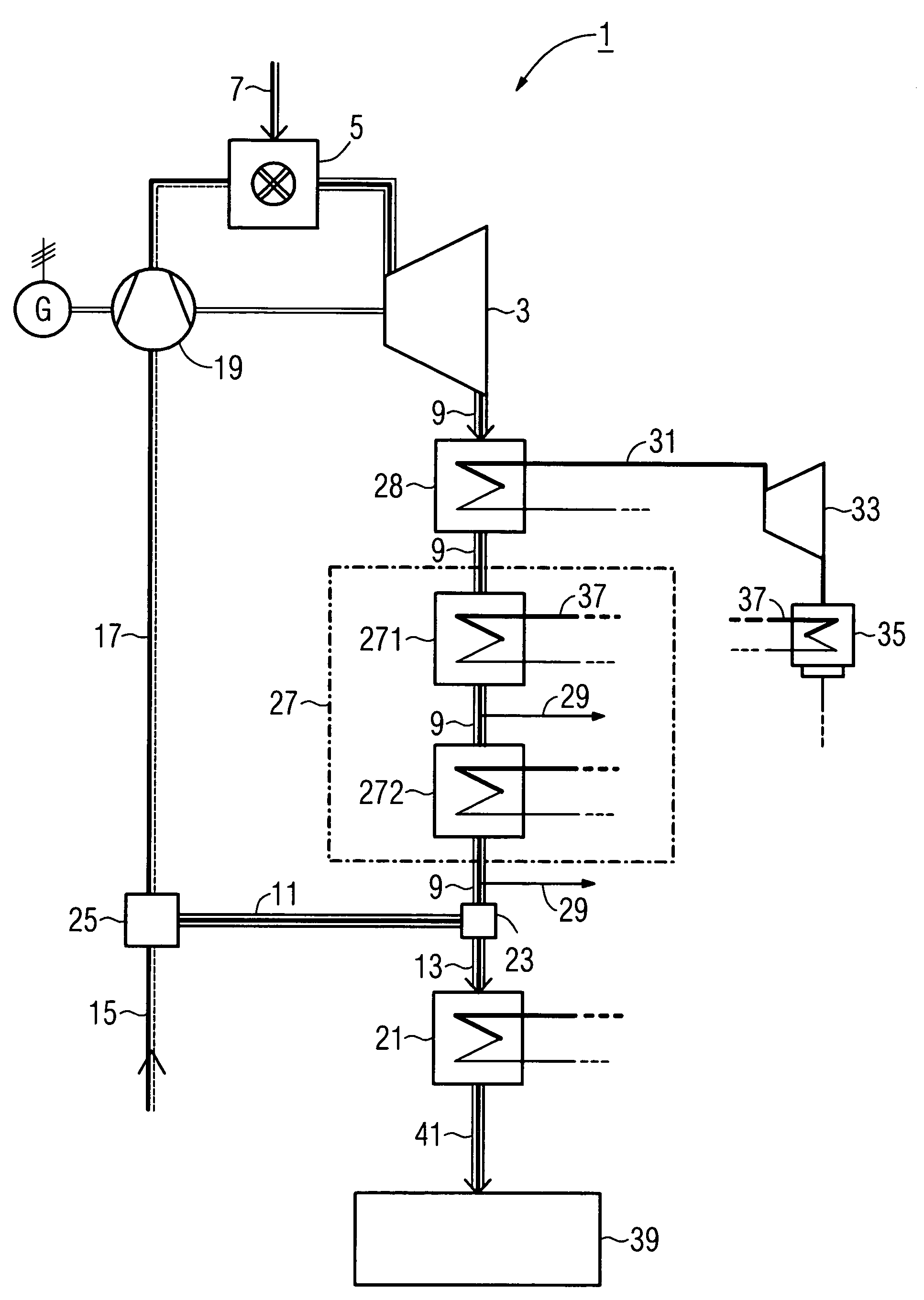
[0046]The FIGURE shows a device 1 according to the invention for operating a gas turbine, said turbine comprising a free power turbine 3, a combustion chamber 5, and a condenser 19. The device 1 is embodied as a gas and steam power station.

[0047]A hot gas made ready in the combustion chamber 5 is made to impinge on the free power turbine 3. A fossil fuel 7 is channeled to and burned in the combustion chamber 5 for this.

[0048]On completion of work, the still hot gas exits the free power turbine 3 in the form of exhaust gas 9 and is channeled to a waste-heat steam generator 28, by means of which process steam 31 is generated for a steam turbine 33. Said type of coupling of the steam turbine 33 to the free power turbine 3 is referred to as a GUD process, which is characterized in particular by a high degree of efficiency in the generation of power.

[0049]To generate electrical energy a generator G is coupled to the free power turbine 3. A further generator, not shown in the FIGURE, is c...


PUM


Abstract

A method according to the invention or a corresponding device (1) provides for dividing exhaust gas (9) exiting the gas turbine into a first (11) and a second partial stream (13), for mixing the first partial stream (11) with combustion air (15), and for channeling the resulting mixture (17) to the combustion chamber (5) and the second partial stream (13) to a carbon dioxide precipitation plant (21).In an advantageous embodiment the exhaust gas (9) exiting the gas turbine (3) is previously used to generate process steam (31) for a steam turbine (33) (gas and steam power station) then cooled before the exhaust gas (9) is divided into said partial streams (11,13). Water (29) precipitating during cooling is removed.

Description

CROSS REFERENCE TO RELATED APPLICATIONS[0001]This application claims priority to the European application No. 02027430.4 EP, filed Dec. 9, 2002 under the European Patent Convention and which is incorporated by reference herein in its entirety.FIELD OF INVENTION[0002]The invention relates to a method and a device for operating a gas turbine with a fossil-fuel fired combustion chamber.BACKGROUND OF INVENTION[0003]One of the progressively more urgent environmental problems of modern times is posed by increasing air pollution, to which noxious substances produced by a wide variety of combustion processes are making a not insubstantial contribution.[0004]The list of such products of combustion is headed in particular by gasses having a harmful impact on the climate such as nitrogen oxides and carbon dioxide.[0005]The environment is also polluted with the above-mentioned climatically harmful gasses produced from generating electrical energy by the burning of fossil fuel.[0006]In the case ...

Claims


Application Information

Patent Timeline
Patent Type & Authority Patents(United States)
IPC IPC(8): F02C6/18F01K23/10F02C3/34
CPCF02C3/34F01K23/10Y02E20/32
Inventor BECKER, BERNARD
Owner SIEMENS AG
Why Eureka
Try Eureka