Laminated turbomachine airfoil with jacket and method of making the airfoil

a turbomachine and airfoil technology, applied in the field of laminated airfoils, can solve the problems of composite materials being fragile and weak under compression or shear, essentially unidirectional strength of composite materials, and preventing laminate separation, the effect of high centrifugal force on the blade and greater thickness

Inactive Publication Date: 2007-11-27
FLORIDA TURBINE TECH
View PDF15 Cites 20 Cited by
  • Summary
  • Abstract
  • Description
  • Claims
  • Application Information

AI Technical Summary

Benefits of technology

[0012]In a second embodiment of the present invention, a turbomachinery blade includes a sheet metal material wrapped around an insert as disclosed in the above first embodiment. The two arm portions are bonded together by brazing. The laminate can optionally be bonded to the insert by brazing. The blade can be formed from one or more sheets of the metal material, where each laminate is bonded to the adjacent laminates. A jacket is secured around the root portion of the blade and extends toward the distal end of the blade just past the critical point such that the jacket prevents separation of the laminate due to high centrifugal force on the blade. The jacket has a greater thickness on the portion near the critical point than at the extreme end of the root portion.

Problems solved by technology

A major drawback of composite blades is their strength is essentially unidirectional.
Despite having a relatively high uniaxial tensile strength, the composite materials are fragile and weak under compression or shear.
However, in gas turbines, the blades are usually under extremely high tensile loads due to high rotational speeds of the rotor disk and blades.
Problems usually arise with regard to the transfer of such loads into the disk.
Since the blades are often made of a metal, the transfer of loads between the two can lead to damage of the fibers, or even worse, delamination of the blade material.
The challenge therefore is to provide an optimum load path between the laminated blade and the surrounding disk.
It is this portion which tends to delaminate or otherwise fail when the blade is loaded and the resulting stresses are applied to the root and interface between the root and disk.
Since composite laminated materials have little ability to handle transverse tension or shear loading, this will result in failure of the composite blade as in blade 10c once the intralaminar tension or shear stresses exceed the ultimate intralaminar stress capabilities of the composite material.
Further, the jacket does not include a thicker portion adjacent to the critical point to produce a compressive force against the laminates due to high centrifugal force acting on the blade.

Method used


Image

  • Laminated turbomachine airfoil with jacket and method of making the airfoil
  • Laminated turbomachine airfoil with jacket and method of making the airfoil
  • Laminated turbomachine airfoil with jacket and method of making the airfoil

Examples


Embodiment Construction

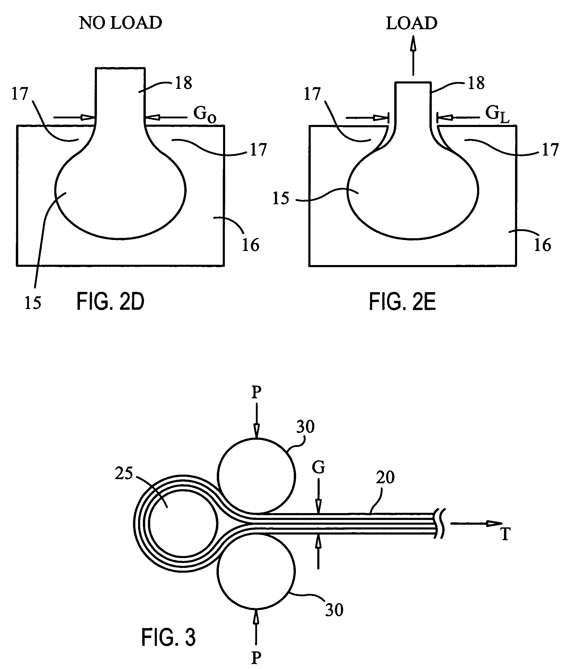
[0026]FIG. 3 is a simplified schematic of the delaminate-preventing principle employed in the present invention. A number of laminates 20 of a material (either a fiber reinforced laminated composite or a sheet metal material) are wrapped around an insert 25, the laminates being bonded together to form the airfoil portion of the blade, the airfoil portion extending along a longitudinal axis 21 of the blade. A point where the laminates digress (or, separate) from one another in the airfoil portion is considered to be a critical point, the critical point being the place where the laminates would begin to delaminate under extreme centrifugal loading of the blade. Cylinders 30 represent a point of contact on the inside surface of the jacket near the critical point. Under extreme centrifugal load, a tensile force T is created along the blade. Since the laminate wraps around the insert 25, the tensile force T will act to pull the insert 25 up against the surface of the cylinders 30. Since ...


PUM


Abstract

An improvement for a turbomachinery blade having an airfoil portion, a neck portion, and a root portion, the neck portion extending from the root portion, and the airfoil portion extending from the neck portion, and the root portion being tear-drop shaped, includes a jacket attached to the root portion and extending along a portion of the neck portion. Additionally, a process of forming a turbomachinery blade includes steps of providing a laminate of a material; providing a blade insert; wrapping the laminate around to insert to form a blade having a root portion, a neck portion extending from the root portion, and an airfoil portion extending from the neck portion; and providing for a jacket secured around the root portion and a portion of the neck portion extending from the root portion, the jacket having such shape as to prevent delamination of the laminates at a critical point due to centrifugal force acting on the blade.

Description

CROSS-REFERENCE TO RELATED APPLICATION[0001]This application is a Continuation-in-part of U.S. Utility patent application Ser. No. 10 / 646,257 filed on Aug. 22, 2003 now U.S. Pat. No. 6,857,856, entitled TAILORED ATTACHMENT MECHANISM FOR COMPOSITE AIRFOILS, which is related to and claims priority from U.S. Provisional application No. 60 / 414,060 filed on Sep. 27, 2002, entitled TAILORED ATTACHMENT MECHANISM FOR COMPOSITE AIRFOILS, the entirety of which is incorporated herein by reference.STATEMENT REGARDING FEDERALLY SPONSORED RESEARCH OR DEVELOPMENT[0002]n / aFIELD OF THE INVENTION[0003]The present invention relates to turbomachinery airfoils, and more specifically to a laminated airfoil used in the compressor section or a gas turbine engine or a compressor.BACKGROUND OF THE INVENTION[0004]Gas turbine engine blades typically have dovetails or roots carried by a slot in a metal rotor disk or drum rotor. A typical blade 1 is shown in FIG. 1 with an airfoil section 2 and a root section 3....

Claims


Application Information

Patent Timeline
Patent Type & Authority Patents(United States)
IPC IPC(8): F01D5/30F01D5/12F01D5/28
CPCF01D5/282F01D5/3092F01D5/3007
Inventor POTTER, BRIANCARTER, BRADRYZNIC, JOHN
Owner FLORIDA TURBINE TECH
Why Eureka
Try Eureka