Power transmission mechanism and manipulator

a transmission mechanism and manipulator technology, applied in the direction of gearing, surgical forceps, hoisting equipment, etc., can solve the problems of increasing the size and cost of the device, reducing the torque, complicating the mechanism, etc., and achieves sufficient rotational rigidity, enhanced fastening force, and improved fidelity to intended works and controllability

Active Publication Date: 2007-11-27
TERUMO KK
View PDF32 Cites 1030 Cited by
  • Summary
  • Abstract
  • Description
  • Claims
  • Application Information

AI Technical Summary

Benefits of technology

[0014]It is therefore an object of the invention to reduce the size and enhance the reliability, rigidity and controllability of various kinds of manipulators.
[0018]According to the invention, the power transmission mechanism using a wire (flexible power transmission element) and pulleys requires no tension adjusting mechanism required in conventional frictional drive systems, and has the structure in which the wire does not interfere with the portion for firmly holding the wire on the pulleys. Therefore, the power transmission mechanism meets the requirements of space saving and multiple rotations. Further, the fastening force is enhanced by the wedge effect. Accordingly, the motion region of the manipulator junction, i.e. the work area of the end effector, is wide enough to allow smooth works. Therefore, the manipulator is greatly improved in fidelity to intended works and in controllability.
[0019]In addition, since at least one of two spans of the wire (the span of the wire subjected to higher tensile force) between the drive pulley and the driven pulley is covered by a hollow elongate member or connected by a solid elongate member, influence of elastic deformation (expansion) of the wire is small enough to assure transmission of sufficient power even when the wire is thin, or the drive pulley and the driven pulley are apart by a long distance. Further, in a hold mode where the drive pulley is stationary or in a servo lock mode, sufficient rotational rigidity is obtained at the driven shaft (output shaft). Therefore, reliable power transmission is assured, and the manipulator is greatly improved in fidelity to intended works and in controllability.
[0020]Moreover, since the manipulator has the configuration free from rotational torque caused by eccentric mass about the connector unit in the basic attitude of the manipulator, which is the most standard attitude in the initial status at the start of controls or during controls, the manipulator is enhanced in fidelity to intended works and in controllability without compelling the operator to exert useless control force. Furthermore, the degrees of freedom of motion have the common rolling axis by the connector unit, bent axis in the aslant direction between the yawing axis (lateral direction) and the pitching axis (vertical direction), and rolling axis. Therefore, it is easy to change the attitude of the work section from the basic attitude, and the manipulator is significantly improved in fidelity to intended works and in controllability.
[0021]That is, it is possible to provide a power transmission mechanism that is compact, lightweight, reliable, rigid and inexpensive, and by incorporating the power transmission mechanism, it is possible to provide a manipulator for assisting surgery or repairing narrow portion in energy devices, which is enhanced in controllability and in fidelity to intended works.

Problems solved by technology

Since the robot forceps have joints for twists, rotations, and other motions, at the end, they can change the attitude of the hand freely, and make suture and ligature from various directions easier, which have been difficult with conventional forceps.
In any of these cases, however, since the drive force basically relies on friction, a decrease of the tensile force, which may occur upon expansion of the wire, causes slips between the wire and the pulleys, and this invites a decrease of the torque.
Therefore, it complicates the mechanism, and increases the size and the cost of the device.
Furthermore, it invites a decrease of the rigidity of the joints.
Usually, surgery-assisting manipulators and manipulators for repairing narrow portions of energy devices, by nature, do not have ample spaces for multiply winding a wire.
However, in case the wire is multiply wound on the pulleys, the motion range (rotation angle) is usually limited to less than 180 degrees because of interference between the fastening member and the wire.
However, the maximum angle is about 270 degrees, and it is difficult to enable rotation of 360 degrees or more.
As far as the rotation range of pulleys is limited, the motion range of the manipulator joint, i.e. the work range of the end effector, remains narrow and will disturb the work by the operator.
Thus, the manipulator largely degrades in fidelity to intended works and controllability.
To assure an ample work region not disturbing the works, the manipulator needs the largest possible number of rotation, but this is difficult with conventional power transmission mechanisms.
In addition, there is the problem that sufficient rotational rigidity is not obtained at the driven shaft (output shaft) in a hold mode where the drive pulley is stationary or in a servo lock mode.
If the desired rotational rigidity is not obtained, then the manipulator degrades in controllability and fidelity to intended works, and operator cannot perform sufficient works.
Depending upon the location of the eccentric mass, rotational torque out of the operator's intention may be produced by the weight about the connector unit, which degrades the controllability.
Especially in the initial status at the start of controls or in the basic attitude of the manipulator, which is the most standard attitude for controls, if rotational torque is produced by eccentric mass about the connector unit, it will impose useless load to the operator and may invite significant degradation of controllability.
In addition, in the manipulator having the common rolling axis, pitching axis and rolling axis as shown in FIG. 25, it is difficult to change the attitude of the work section to the yawing direction (lateral or right-and-left direction) from the basic attitude illustrated because it is the change of attitude to the singular configuration.

Method used


Image

  • Power transmission mechanism and manipulator
  • Power transmission mechanism and manipulator
  • Power transmission mechanism and manipulator

Examples


first embodiment

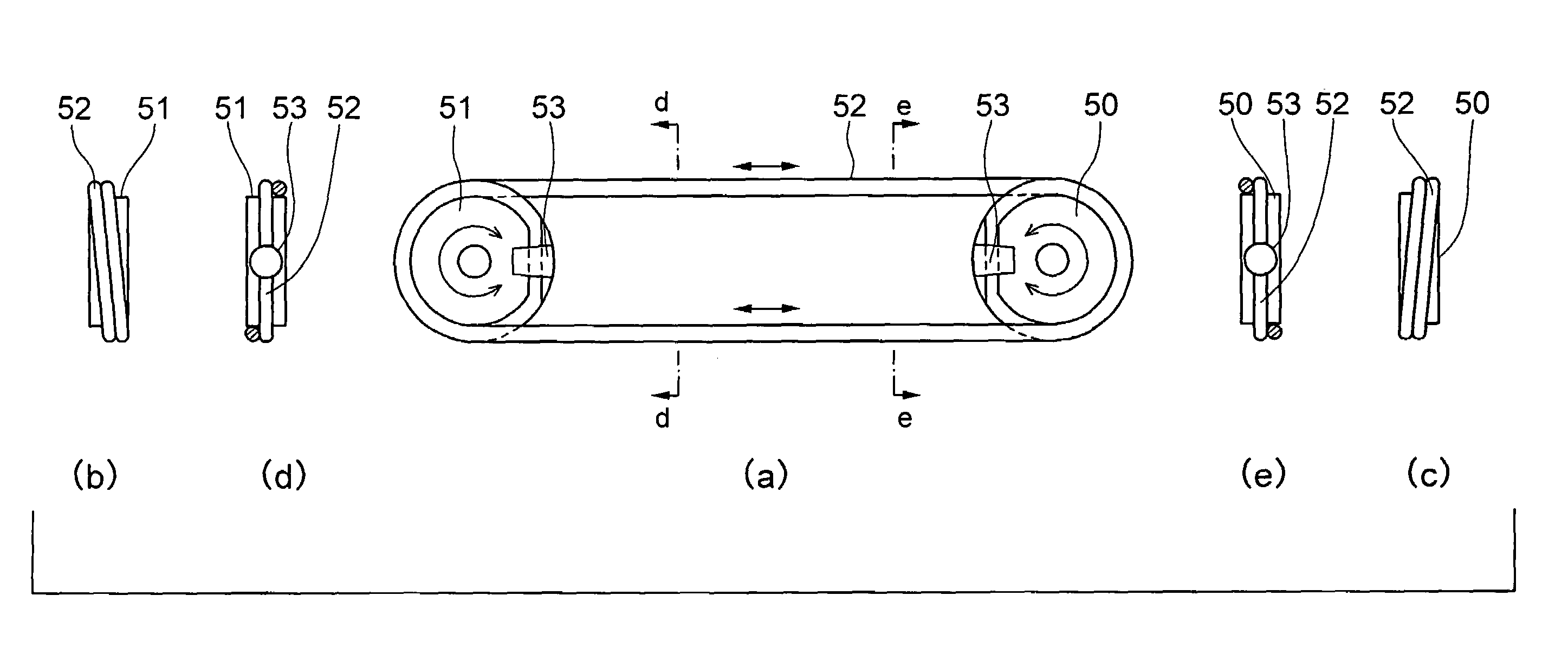
[0057]The wire 52 is loop-shaped, and it is wound on pulleys 5051 by 1.5 turns respectively in this The wire 52 is firmly held on the pulleys 50, 51 by anchor pins 53 (fastening portions). In this configuration, the maximum motion range of ±270 degrees is obtained.

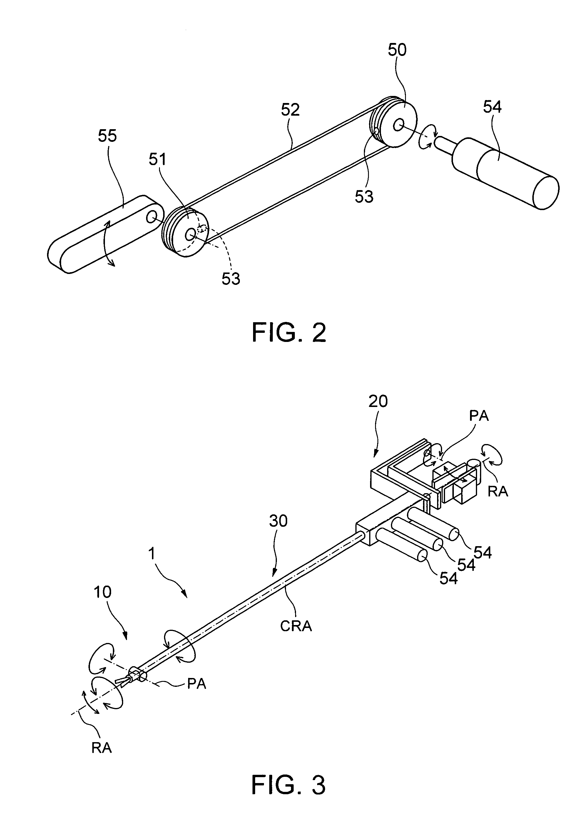
[0058]FIG. 2 shows an example of the entire power transmission system in which a motor 54 with a reducer is associated with the drive pulley 50 whereas an arm 55 is associated with the driven pulley 51. However, the system is not limited to this configuration. Basically, the system is a power transmission mechanism for transmitting power from the drive side to the driven side. Similarly, although FIG. 3 shows an example of incorporating the system in a manipulator 1, combination of the system and the manipulator 1 is not limited to this configuration. The manipulator 1 is composed of a work unit 10, control unit 20, connector unit 30, control unit (not shown), and others, and the operator adjusts the position and attitude...

second embodiment

[0063]FIGS. 8 through 12 are simplified sectional views of the wire / pulley portions at the drive side and the lower side in a power transmission mechanism of a manipulator according to the invention. Here are shown examples of the use of a hollow tube (as a hollow elongate member, also in the description herein below) covering one or both of the spans of the wire 52 between the pulleys 50 and 51, or the use of a solid cord (or a solid rod, as a solid elongate member, also in the description herein below) connecting one or both of the spans of the wire 52 between the pulleys 50 and 51. As shown n these figures, there are various possible ways of connecting the wire 52 to the pulleys, and any of them is employable without problems. In the examples shown in FIG. 9 and FIG. 11, the wire 52 need not pass through the lower hollow tube 60a, but it may be secured to the hollow tube 60a at two or more different points. Since the pull strength of the portions of fixture is usually lower than ...

third embodiment

[0068]FIGS. 15 through 20 are perspective views of manipulators according to the invention and diagrams showing their wire / pulley portions. In the master-slave combined manipulator conjoining the master and the slave, the center of gravity of the driving device is remote from the connector unit 30. Therefore, eccentric mass about the connector unit 30 is produced in most cases. Depending upon the position of the eccentric mass, rotational torque out of the operator's intention may be produced about the connector unit 30 by influences of the gravity, and this may invite degradation of the controllability. Especially in the initial status at the start of controls of the manipulator or in the basic attitude of the manipulator, which is the most standard attitude for controls, if rotational torque is produced by eccentric mass about the connector unit, it will impose useless load to the operator and may invite significant degradation of controllability.

[0069]In most cases, it is the dri...


PUM


Abstract

A power transmission mechanism comprising: a flexible power transmission element; a pair of a drive pulley and a driven pulley on which the flexible power transmission element is wound, each the pulley having a pin-embedding hole formed to extend from the outer circumferential thereof toward the center thereof, and a slit elongated in the circumferential direction of the pulley to extend to opposite sides of the embedding hole and communicating with the embedding hole; and a pair of columnar or tapered anchor pins each having a path hole penetrating the anchor pin across the lengthwise direction thereof to receive the flexible power transmission element inserted therein, wherein each the anchor pin receiving the flexible power transmission element in the path hole thereof is embedded in the embedding hole of the associated pulley under pressure, and the flexible power transmission element is thereby held on the pulley.

Description

CROSS-REFERENCE TO RELATED APPLICATION[0001]This application is based upon and claims the benefit of priority from prior Japanese Patent Application No. 2003-96446, filed on Mar. 31, 2003, the entire contents of which are incorporated herein by reference.BACKGROUND OF THE INVENTION[0002]1. Field of the Invention[0003]The present invention relates to a manipulator such as an operation-aiding manipulator or a manipulator for repairing a narrow portion of an energy device or the like. Especially, the present invention is intended to provide a power transmission mechanism using a wire and pulleys, which can be reduced in size and can be enhanced in reliability, rigidity and user-friendliness.[0004]2. Related Background Art[0005]In conventional laparoscope-assisted surgery such as laparoscopic cholecystectomy, a laparoscope 161, forceps 171, 172, etc. are inserted into an abdominal cavity through trocars 154 set in small incisions 151, 152, 153 made in the abdomen of a patient 150. Then,...

Claims


Application Information

Patent Timeline
Patent Type & Authority Patents(United States)
IPC IPC(8): F16H7/06A61B19/00B25J3/00B25J9/10B25J17/00F16H7/04F16H7/18F16H19/02
CPCA61B17/0469F16H7/04A61B19/2203B25J9/104A61B19/22A61B2017/00371A61B2017/00398A61B2017/2902A61B2017/292A61B2017/2927A61B2017/2929A61B2017/2932A61B2017/294A61B2019/2234A61B2019/2242A61B2019/2246A61B2034/715A61B34/70A61B34/71A61B34/30A61B2034/305B65G1/02
Inventor JINNO, MAKOTOMIYAGAWA, TOYOMITSUKADA, SHIROKUDO, AKIRA
Owner TERUMO KK
Why Eureka
Try Eureka