Microscope device

a microscope and lens technology, applied in the field of microscope devices, can solve the problems of restricting the freedom of device design, and achieve the effect of reducing at least the restriction on the design freedom of the devi

Inactive Publication Date: 2007-11-27
FUJI PHOTO OPTICAL CO LTD
View PDF8 Cites 3 Cited by
  • Summary
  • Abstract
  • Description
  • Claims
  • Application Information

AI Technical Summary

Benefits of technology

[0009]In view of the above-described circumstances, an object of the present invention is to provide a microscope device capable of improving the S / N, contrast and resolution of an image like the confocal microscope while reducing at least the restriction on the device design freedom due to the adjustment of the placement of the pin hole plate at a predetermined position.

Problems solved by technology

The confocal microscope has a number of improved effects but has a problem that restrictions are imposed on the freedom of device design, because it is necessary to adjust the pin hole plate to the predetermined position before the image pickup plane on condition that the above-mentioned three positions are set in a conjugate relationship, and because in ordinary cases there is a need to place the pin hole plate in a stage following the light source to form a point light source.

Method used


Image

  • Microscope device
  • Microscope device
  • Microscope device

Examples


first embodiment

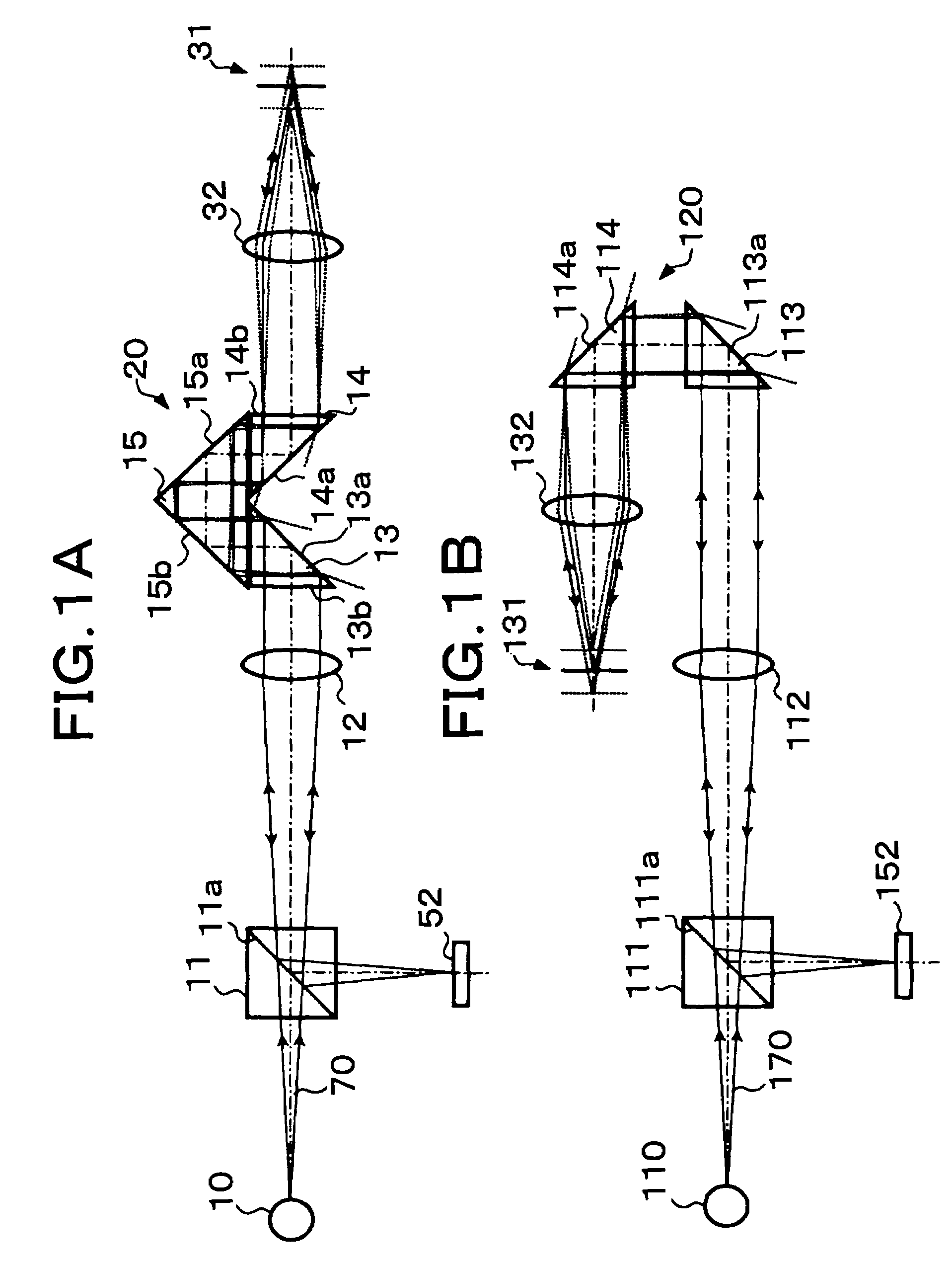
[0043]FIG. 1A shows the configuration of the

[0044]A light beam 70 emitted from a point light source 10 travels through a half prism 11, a collimator lens 12, a parallel beam selection means 20 and an objective lens 32 to be converged at a desired position on an object 31. The light beam emitted from the point light source 10 is in a divergent state but it is formed into a parallel beam along an optical axis by the collimator lens 12, so that substantially the entire light beam passes through the parallel beam selection means 20. When the parallel light beam that has passed through the parallel beam selection means 20 is converged on the above-mentioned desired position by the objective lens 32, the desired position coincides with the focal point of the objective lens 32.

[0045]If the entire reflected light from the above-mentioned desired position (convergence position) on the object 31 is specularly reflected light, it is supposed to be converted into a parallel light beam by the ob...

second embodiment

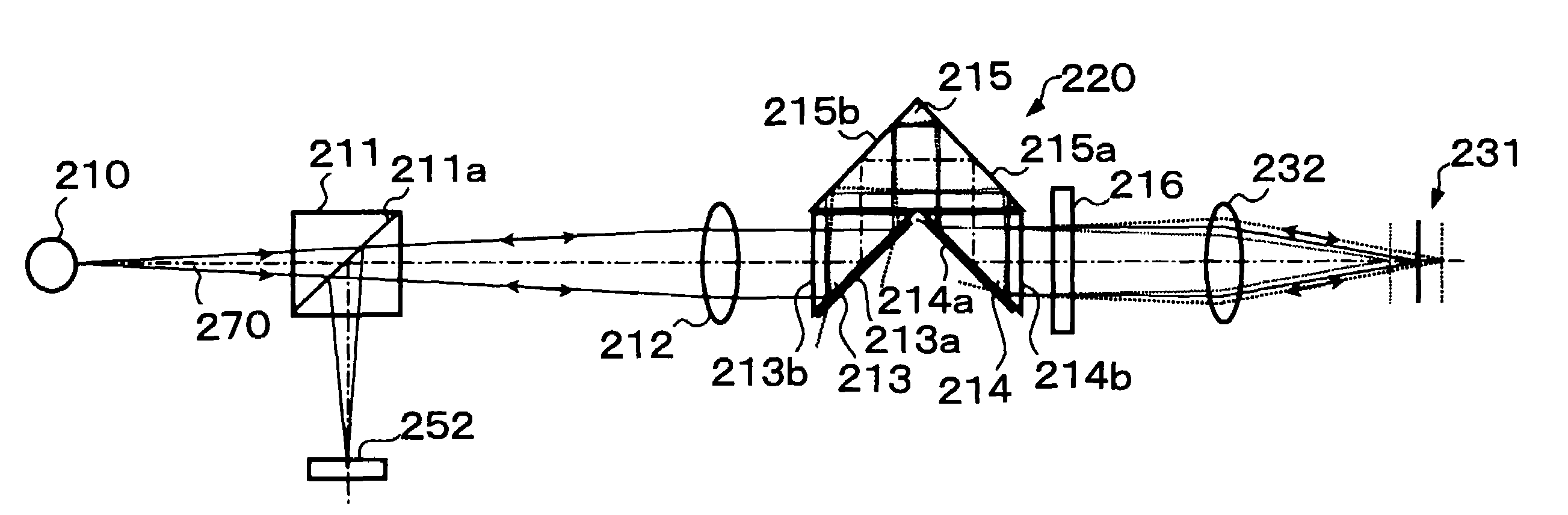
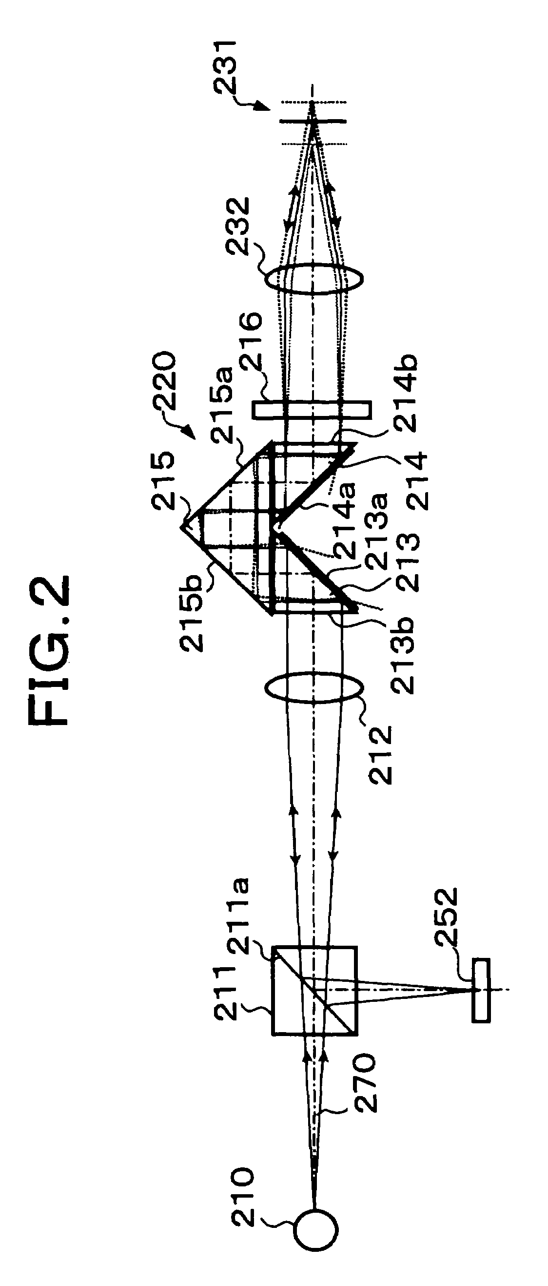
[0052]In the second embodiment shown in FIG. 2, a polarization beam splitter 211 is provided in place of the above-described half prism 11, and a ¼ wavelength plate 216 is provided between a parallel beam selection means 220 and an objective lens 232.

[0053]In the second embodiment, illumination light transmits through the polarization beam splitter 211 to be converted into one linear polarization (s-polarization), and return light is converted into another linear polarization (p-polarization) by transmitting through the ¼ wavelength plate 216 two times. Therefore, generally the entire light beam returned to the polarization beam splitter 211 is reflected by a polarization reflecting surface 211a. In this way, a fine light spot carrying object information can be obtained with efficiency.

[0054]Each of oblique surfaces 213a and 214a of two critical-angle prisms 213 and 214 in the parallel beam selection means 220 is coated with an optical thin film for increasing the amount of reflecti...

third embodiment

[0057]The third embodiment shown in FIGS. 3A and 3B is arranged so that an object surface (convergence surface) 331 or 431 is one-dimensionally or two-dimensionally scanned with a light beam emitted from a parallel beam selection means 320 or 420. That is, one-dimensional or two-dimensional scanning with the light beam is performed by means of an optical scanner 321 or 421, e.g., a galvanometer mirror or a polygon mirror placed on the light source 310 or 410 side of an objective lens 332 or 432. It is possible to one-dimensionally or two-dimensionally obtain information on the object surface 331 or 431 by scanning the object surface with the illumination light beam in this manner.

[0058]In the arrangement shown in FIG. 3A, the illumination light beam is emitted to the optical scanner 321 in a state of being formed as a parallel light beam. In the arrangement shown in FIG. 3B, the illumination light beam is emitted to the optical scanner 421 while being converged from the parallel bea...


PUM


Abstract

Specularly reflected light from a convergence position on an object surface 31 enters a second critical-angle prism 14, another prism 15, and a first critical-angle prism 13 of a parallel beam selection optical system 20 in this order as a parallel beam traveling along the optical axis. The critical-angle prisms 13, 14 have critical angles of 45 degrees with respect to the wavelength of the light beam. Light beams other than the parallel light beam are removed at oblique surfaces 13a, 14a of the critical-angle prisms 13, 14, thereby allowing only the parallel light beam to exit as a regular light beam. This parallel beam is formed into a convergent light by a collimator lens 12, reflected by a half prism 11 and converged on an image pickup surface of an image pickup device 52. In this way, unnecessary noise light can be removed without placing a pin hole plate such as that placed before the image pickup plane in a confocal microscope.

Description

RELATED APPLICATIONS[0001]This application claims the priority of Japanese Patent Application No. 2003-430029 filed on Dec. 25, 2003, which is incorporated herein by reference.BACKGROUND OF THE INVENTION[0002]1. Field of the Invention[0003]The present invention relates to a microscope device which irradiates an object with probe light and receives reflected light from the object to obtain an image of the object and, more particularly, to a microscope device capable of obtaining an image of an object such as a human body tissue having an extremely large proportion of scattering light.[0004]2. Description of the Prior Art[0005]A confocal microscope for obtaining an image of an object for a medical or industrial purpose for example is known.[0006]In the known confocal microscope, a point light source, a position at which an object is focused and a pin hole provided before an image pickup plane are placed in a conjugate positional relationship with each other, and reflected light from a...

Claims


Application Information

Patent Timeline
Patent Type & Authority Patents(United States)
IPC IPC(8): G02B21/06G02B21/00
CPCG02B21/0032
Inventor KOHNO, SHINICHI
Owner FUJI PHOTO OPTICAL CO LTD
Why Eureka
Try Eureka