Wireless packet transfer apparatus and method

a wireless packet and apparatus technology, applied in the field of circuit switched wireless communication system, can solve the problems of packet loss, long time-consuming data transmission, and reduced throughput by retransmission, and achieve the effect of efficiently transferring wireless packets

Inactive Publication Date: 2007-11-27
KOKUSA ELECTRIC CO LTD
View PDF11 Cites 99 Cited by
  • Summary
  • Abstract
  • Description
  • Claims
  • Application Information

AI Technical Summary

Benefits of technology

[0017]According to the second invention, therefore, when a packet sent form a network is transferred to a wireless transmission path, the transmission condition is judged in the packet unit. Error processing for an error packet is performed in correspondence with the judged transmission condition. Therefore, for example, if a reception packet has an error and if a protocol or application itself of the reception packet has an error correction ability or an error permission ability, the reception packet is transferred directly to the network. If the protocol or application itself of the reception packet does not have an error correction ability or an error permission ability, the reception packet is discarded. In this manner, the error processing becomes possible by considering the function of the protocol or application of a packet. Therefore, also in the second invention, a wireless packet transmission of a high throughput can be realized even in a circuit switched system, while a desired communication service quality of each packet is maintained.
[0019]Therefore, according to the present invention, a wireless packet transfer apparatus can be provided which can transfer a wireless packet efficiently even in a circuit switched system, while a desired communication service quality of each packet is maintained.

Problems solved by technology

Using IP for wireless communication systems of this type is associated with the following problems.
The first problem is that it takes a long time for data transmission because a transmission bandwidth is narrow (about 25.6 Kbit / s at a maximum transmission speed).
The second problem is a throughput lowered by re-transmission caused by packet loss and a reduction in a window size of Transmission Control Protocol (TCP) and the like, because of a high bit error rate (10−3 to 10−4) of a transmission line.
The third problem is a fixed error correction encoding rate of each call because of circuit switching.
Since a predetermined error correction encoding is performed for data transmission even in a good quality state of a wireless propagation path, the transmission bandwidth cannot be used efficiently.
The fourth problem is that if a router or the like is used as an interface between wireless apparatus and a network, an error packet is unconditionally discarded because of a data link protocol of the router.
Therefore, even if an application having a bit error permission function, such as MPEG4, is used, the whole packet is lost because of a bit error so that the image quality is degraded.
However, the wireless TCP cannot provide a TCP connection of end-to-end and the mount of an agent is complicated.

Method used


Image

  • Wireless packet transfer apparatus and method
  • Wireless packet transfer apparatus and method
  • Wireless packet transfer apparatus and method

Examples


first embodiment

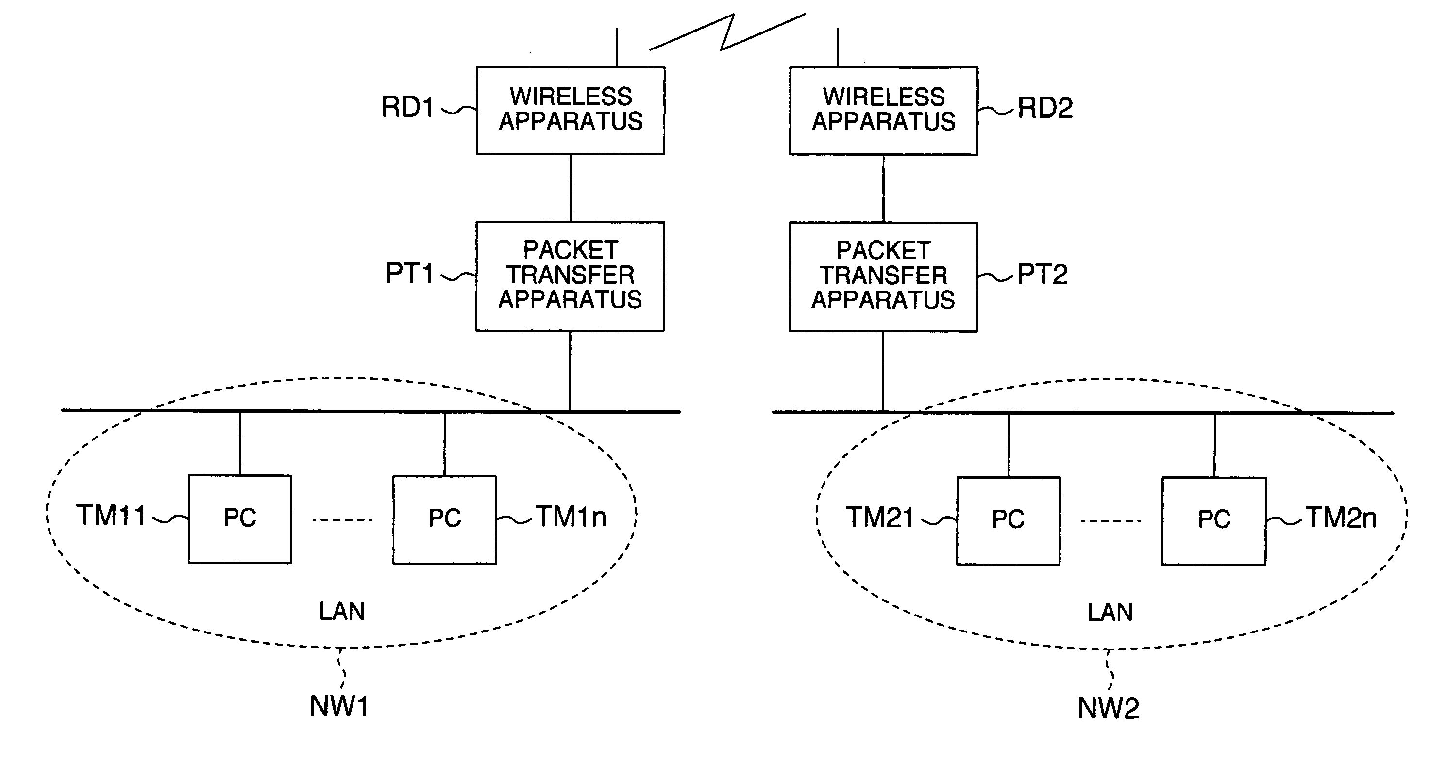
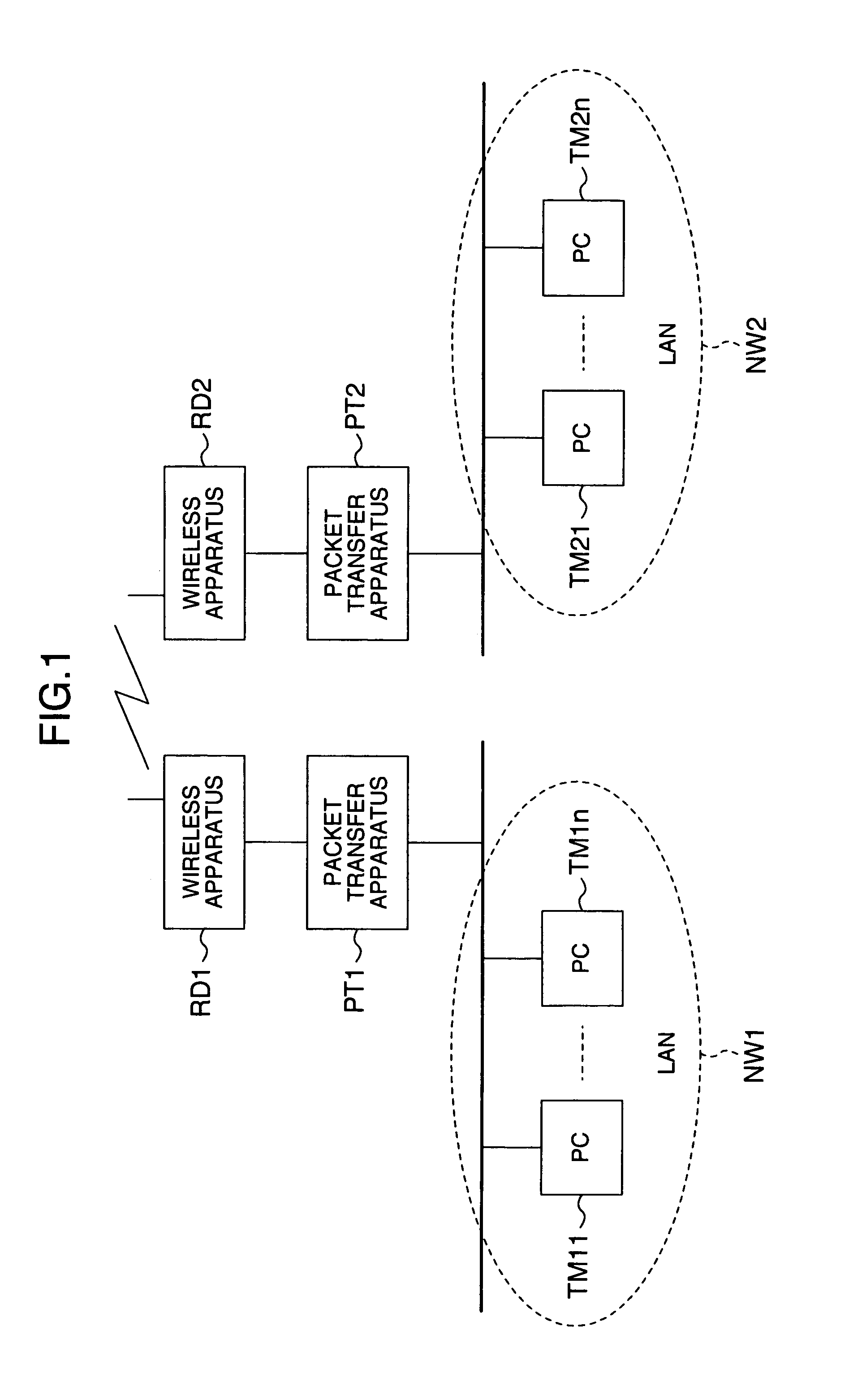
[0039]FIG. 1 is a schematic diagram showing the configuration of an anti-disaster wireless communication system using wireless packet transfer apparatuses according to the first embodiment of the present invention.

[0040]This system has first and second networks NW1 and NW2. These networks NW1 and NW2 are installed, for example, in prefectural or municipal offices of a self-governing body, and configured by wired Local Area Network (LAN). The networks NW1 and NW2 accommodate a plurality of information communication terminals TM11 to TM1n, and TM21 to TM2m, respectively. The networks NW11 and NW2 are connected to wireless apparatuses RD1 and RD2 via packet transfer apparatuses PT1 and PT2, respectively. These packet transfer apparatuses PT1 and PT2 and wireless apparatuses RD1 and RD2 are used for transferring packets between the first and second networks NW1 and NW2 via a wireless transmission path.

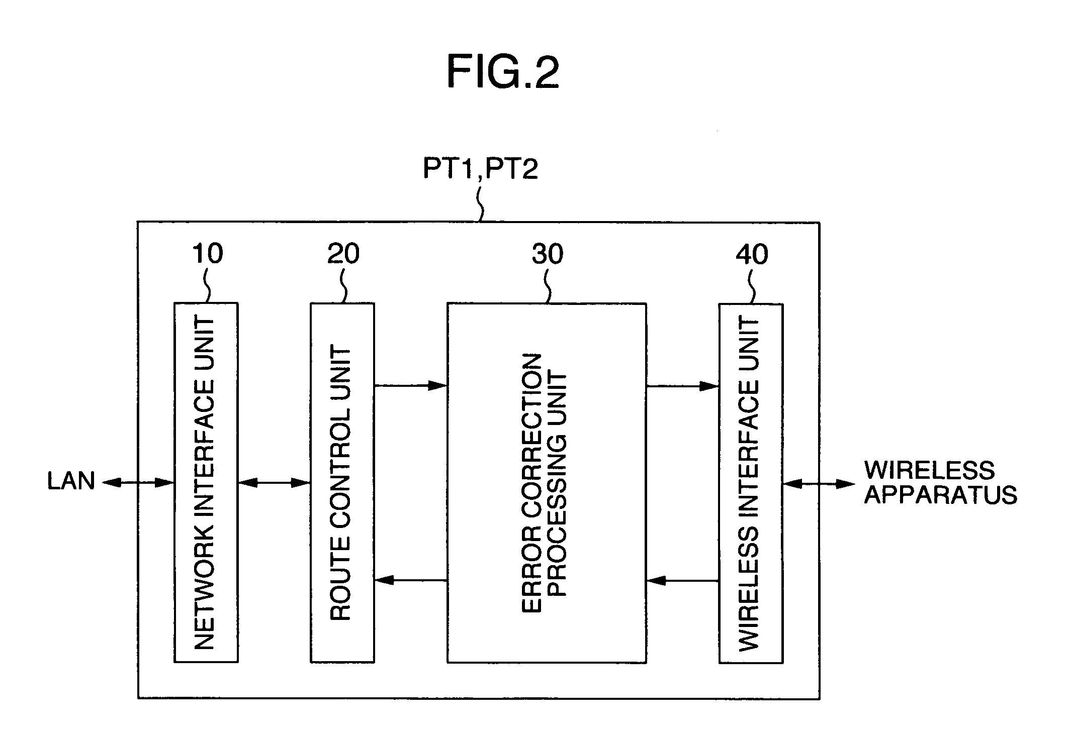
[0041]As shown in FIG. 2, the packet transfer apparatuses PT1 and PT2 each have a netw...

second embodiment

[0083]The second embodiment of the present invention uses an error correction encoding rate selection table considering a wireless propagation quality, and an error correction encoding rate is selected in accordance with an estimated value of a propagation quality of a wireless transmission path and the error correction encoding rate selection table, and in accordance with the selected encoding rate, a transmission packet is subjected to error correction encoding and transferred to a wireless transmission path.

[0084]FIG. 12 is a diagram showing the structure of the error correction encoding rate selection table provided in the packet transfer apparatus according to the second embodiment of the present invention. The whole structure of an anti-disaster wireless communication system and the structures of packet transfer apparatuses PT1 and PT2 and an error correction processing unit 30 are similar to those shown in FIGS. 1 to 3, and the detailed description thereof is omitted.

[0085]As...

third embodiment

[0090]The third embodiment of the present invention uses an error correction encoding rate selection which stores a preset error correction encoding rate necessary for maintaining a desired QoS, in correspondence with a protocol type and an application type and a propagation quality of a wireless transmission path. For each transmission packet, the protocol type and application type and an estimated BER of the wireless communication path are acquired. In accordance with the acquired information, an error correction encoding rate is selected from the error correction encoding rate selection table. In accordance with the selected encoding rate, the transmission packet is subjected to error correction encoding and transferred to the wireless transmission path.

[0091]FIG. 14 is a diagram showing the structure of the error correction encoding rate selection table provided in the packet transfer apparatus according to the third embodiment of the present invention. Also in this embodiment, ...


PUM


Abstract

An error correction encoding rate selection table is provided in an error correction processing unit of a packet transfer apparatus, and the table stores an error correction encoding rate preset to maintain a desired QoS in correspondence with a protocol type and an application type. When a transmission packet is transferred to a wireless transmission path, an encoding control unit judges the protocol type and application type of a transmission packet from a header of the transmission packet, in accordance with a judgment result and the error correction encoding rate selection table, an error correction encoding rate is selected, and the transmission packet is subjected to error correction encoding and transferred.

Description

INCORPORATION BY REFERENCE[0001]The present application claims priority from Japanese application JP2004-171153 filed on Jun. 9, 2004, the content of which is hereby incorporated by reference into this application.BACKGROUND OF THE INVENTION[0002]1. Field of the Invention[0003]The present invention relates to a circuit switched wireless communication system such as an anti-disaster wireless communication system, and more particularly to a wireless packet transfer apparatus for transferring a packet by wireless by using Internet Protocol (IP).[0004]2. Description of the Related Art[0005]With the recent advancement of IP networks, various applications are provided by using IP. It is expected that seamless communications of IP are realized even among different types of networks such as wired and wireless networks, by adopting new technologies such as mobile IPv6 (IP version 6).[0006]A public utility wireless communication system such as an anti-disaster wireless communication system ge...

Claims


Application Information

Patent Timeline
Patent Type & Authority Patents(United States)
IPC IPC(8): H04Q7/24H04L1/00H04L12/70H04L29/06H04W28/00H04W28/04
CPCH04L1/0009H04L1/0016H04L1/208H04L1/0069H04L1/0072H04L1/0059
Inventor NAKABAYASHI, SUMIEADACHI, MASARU
Owner KOKUSA ELECTRIC CO LTD
Why Eureka
Try Eureka