
Channel estimation in a spread spectrum receiver

a spread spectrum receiver and channel estimation technology, applied in the field of wireless communication systems, can solve the problems of adversely affecting the received rf signal, distorted rf signal received by the receiver from the rf signal transmitted by the transmitter, complex and vital function of channel estimation, etc., and achieve the effect of accurate determination

Inactive Publication Date: 2007-11-27
AVAGO TECH WIRELESS IP SINGAPORE PTE
View PDF10 Cites 12 Cited by
  • Summary
  • Abstract
  • Description
  • Claims
  • Application Information

AI Technical Summary

Benefits of technology

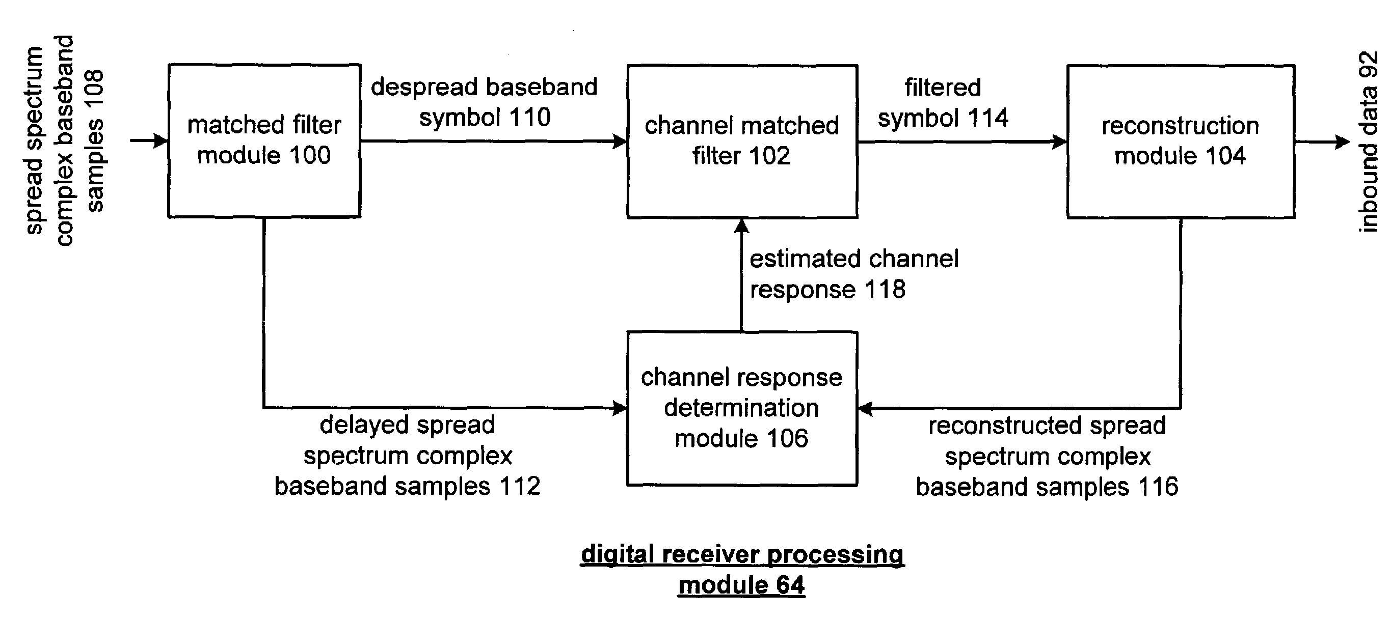
[0010]The channel estimation in a spread spectrum receiver of the present invention substantially meets these needs and others. In one embodiment, a channel estimation module for use in a spread spectrum receiver includes a matched filter module, channel matched filter, reconstruction module and channel response determination module. The matched filtered module is operably coupled to produce a despread baseband symbol and delayed spread spectrum complex baseband samples from received spread spectrum complex baseband samples. In one embodiment, the matched filter module may be implemented utilizing a Barker matched filter having finite impulse response (FIR) filter matched to an eleven bit Barker sequence. Due to the full length and partial length auto correlation properties of a Barker sequence, the despread baseband symbol may be accurately determined even though errors exist in the received spread spectrum complex baseband signal caused by the channel.
[0013]The channel response determination module is operably coupled to generate the estimated channel response based on the delayed spread spectrum complex baseband samples, which have been adversely affected by the channel response, and the reconstructed spread spectrum complex baseband samples, which has not been adversely affected by the channel response. In one embodiment, the channel response determination module may use a least mean square algorithm based channel estimator that effectively generates an estimated channel response that essentially accounts for both the gain and phase profiles at various delays for the entire channel. The resulting estimated channel response includes coefficients that, when provided to the channel matched filter, enables the channel matched filter to maximize signal to noise ratio at its output, thus substantially mitigating the adverse effects caused by the channel response.

Problems solved by technology

In practice, however, the RF signal received by the receiver has been distorted from the RF signal transmitted by the transmitter due to the frequency response of the channel carrying the RF signal, i.e., the channel response.
For instance, multi-path effects, distance, transmit power levels, et cetera all effect the channel response and consequently, adversely affect the received RF signal.
Needless to say, channel estimation is a complex and vital function for accurate wireless communications.
Even though the channel estimation circuitry is operating at very high rates, the processing takes multiple iterations to obtain the coefficients, which is time consuming and requires complex hardware.
In some applications, there is not sufficient time to completely train the channel estimation circuitry even though it is operating at very high rates.
When the preamble includes the short SYNC data unit, which is 56 microseconds in length, current channel estimation circuitry cannot obtain a reliable channel estimation for an entire multipath channel in such a short time, so compromises are made.
For instance, only the three most prominent paths of the multi-path channel are used, which reduces the accuracy of channel equalization.

Method used


Image

  • Channel estimation in a spread spectrum receiver
  • Channel estimation in a spread spectrum receiver
  • Channel estimation in a spread spectrum receiver

Examples


Embodiment Construction

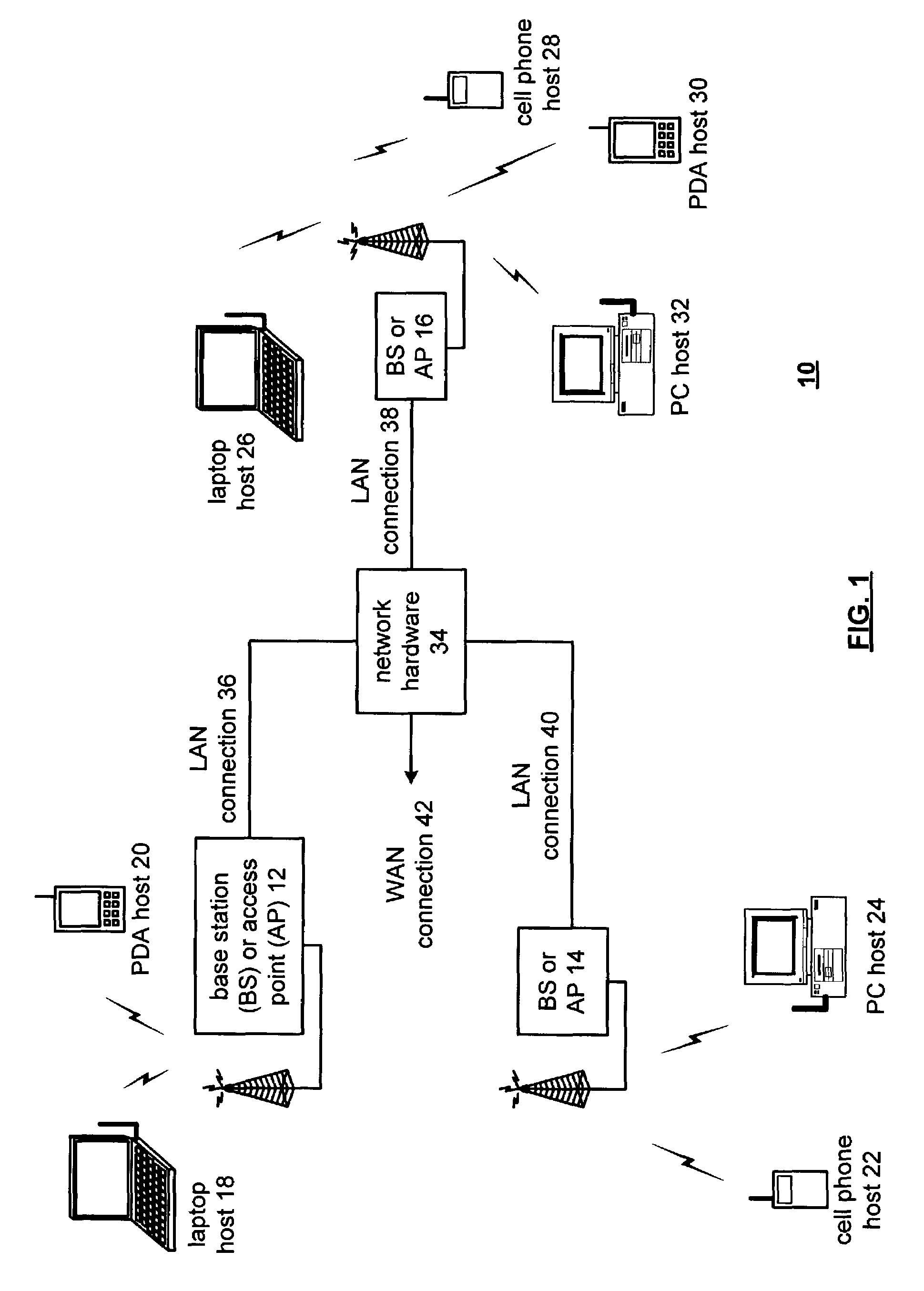
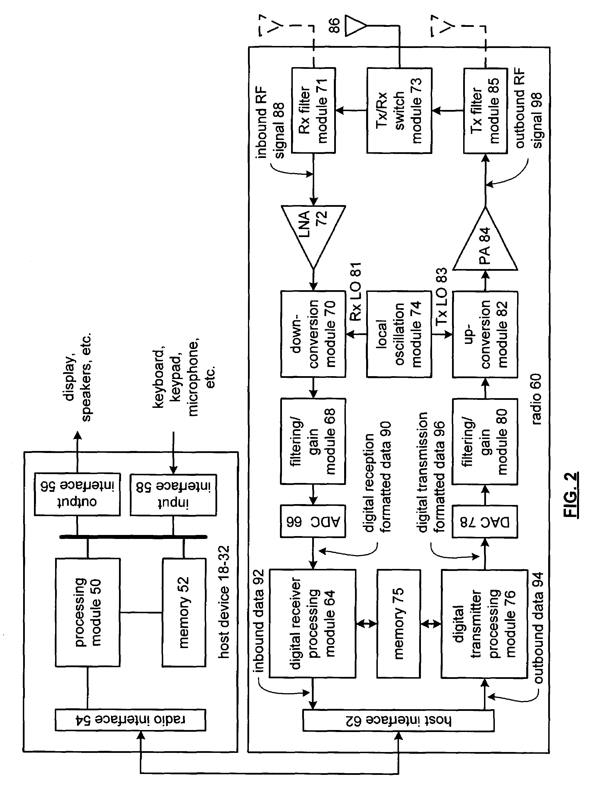
[0025]FIG. 1 is a schematic block diagram illustrating a communication system 10 that includes a plurality of base stations and / or access points 12-16, a plurality of wireless communication devices 18-32 and a network hardware component 34. The wireless communication devices 18-32 may be laptop host computers 18 and 26, personal digital assistant hosts 20 and 30, personal computer hosts 24 and 32 and / or cellular telephone hosts 22 and 28. The details of the wireless communication devices will be described in greater detail with reference to FIG. 2.

[0026]The base stations or access points 12-16 are operably coupled to the network hardware 34 via local area network connections 36, 38 and 40. The network hardware 34, which may be a router, switch, bridge, modem, system controller, et cetera provides a wide area network connection 42 for the communication system 10. Each of the base stations or access points 12-16 has an associated antenna or antenna array to communicate with the wirele...


PUM


Abstract

A method and apparatus for channel estimation in a spread spectrum receiver include processing that begins by despreading a received spread spectrum complex baseband sample utilizing a pseudorandom spreading sequence to produce a despread baseband symbol. The processing continues by filtering the despread baseband symbol to attenuate adverse channel effects based on a channel response estimate to produce a filtered despread baseband symbol. The processing then continues by decoding the filtered despread baseband symbol to produce recaptured data. The processing continues by modulating the recaptured data to produce a remodulated symbol. The processing then continues by producing a reconstructed spread spectrum complex baseband sample from the remodulated symbol based on the pseudorandom spreading sequence. The processing then continues by generating the channel response estimate such that a convolution of the channel response estimate with the reconstructed spread spectrum complex baseband sample substantially emulates the received spread spectrum complex baseband sample.

Description

TECHNICAL FIELD OF THE INVENTION[0001]This invention relates generally to wireless communication systems and more particularly to spread spectrum receivers used within such wireless communication systems.BACKGROUND OF THE INVENTION[0002]Communication systems are known to support wireless and wire lined communications between wireless and / or wire lined communication devices. Such communication systems range from national and / or international cellular telephone systems to the Internet to point-to-point in-home wireless networks. Each type of communication system is constructed, and hence operates, in accordance with one or more communication standards. For instance, wireless communication systems may operate in accordance with one or more standards including, but not limited to, IEEE 802.11, Bluetooth, advanced mobile phone services (AMPS), digital AMPS, global system for mobile communications (GSM), code division multiple access (CDMA), local multi-point distribution systems (LMDS), ...

Claims


Application Information

Patent Timeline
Patent Type & Authority Patents(United States)
IPC IPC(8): H04B1/00H04B1/707H04L25/02
CPCH04L25/0232H04B1/7093
Inventor IBRAHIM, BRIMADESAI, PRASANNA
Owner AVAGO TECH WIRELESS IP SINGAPORE PTE
Learn More