
3-D structures with smoothly-varying topographical features in photo-sensitive epoxy resists

a technology of epoxy resist and topographical features, which is applied in the field of photoresist material processing, can solve the problems of resist full thickness removal, uv light not being able to adequately penetrate the deeper-lying volumes of positive photoresist, and resist thickness

Inactive Publication Date: 2007-12-04
AFROMOWITZ MARTIN A
View PDF14 Cites 15 Cited by
  • Summary
  • Abstract
  • Description
  • Claims
  • Application Information

AI Technical Summary

Benefits of technology

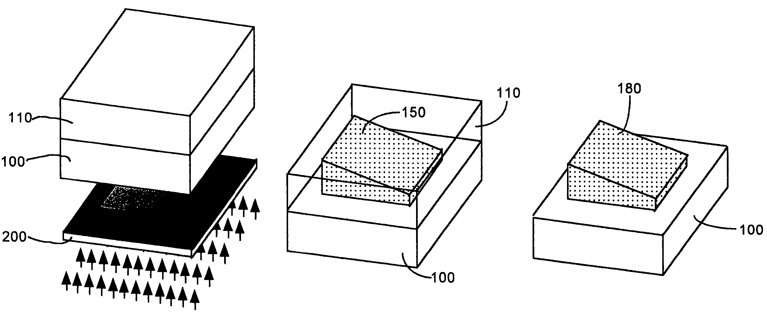
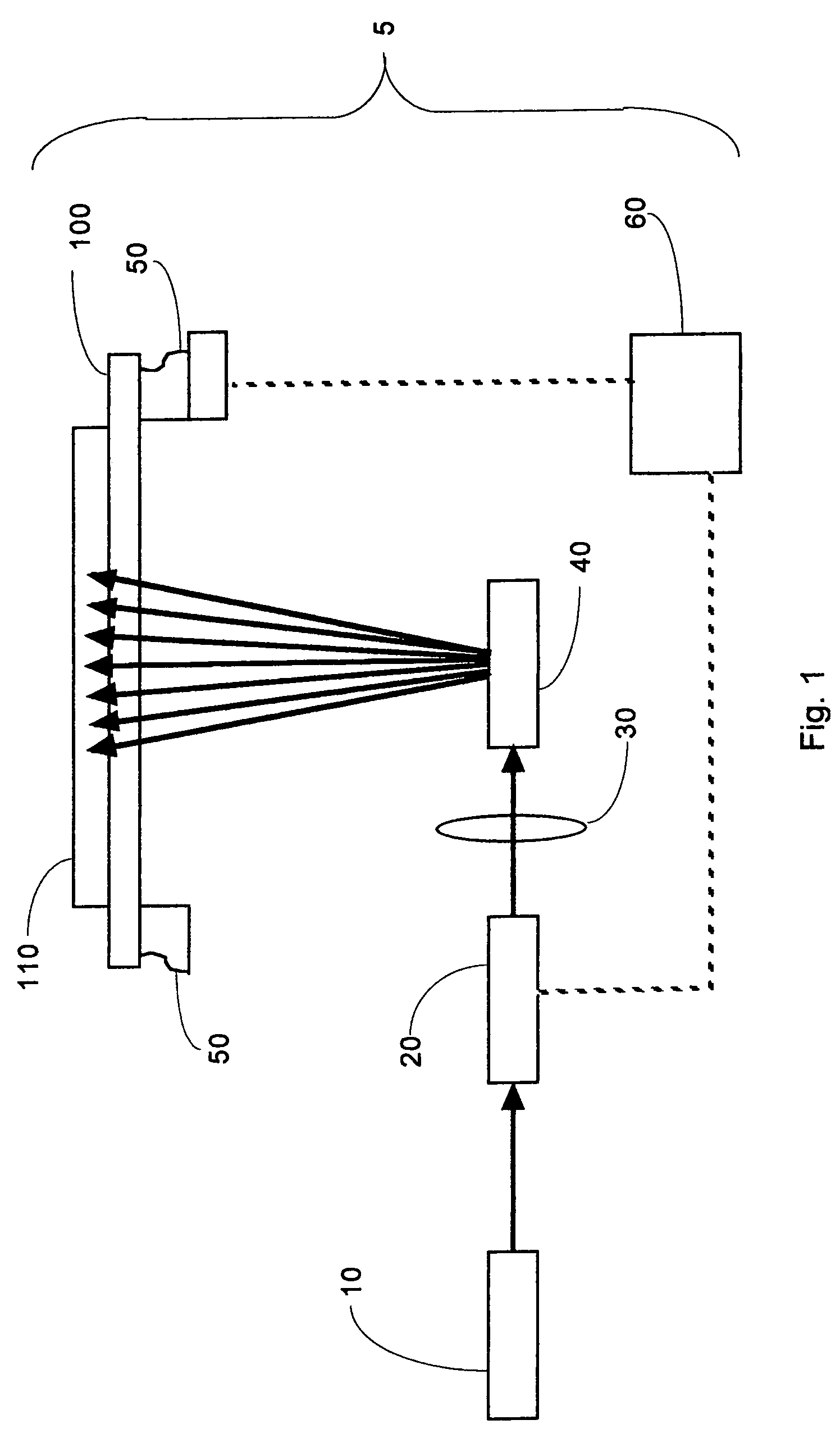
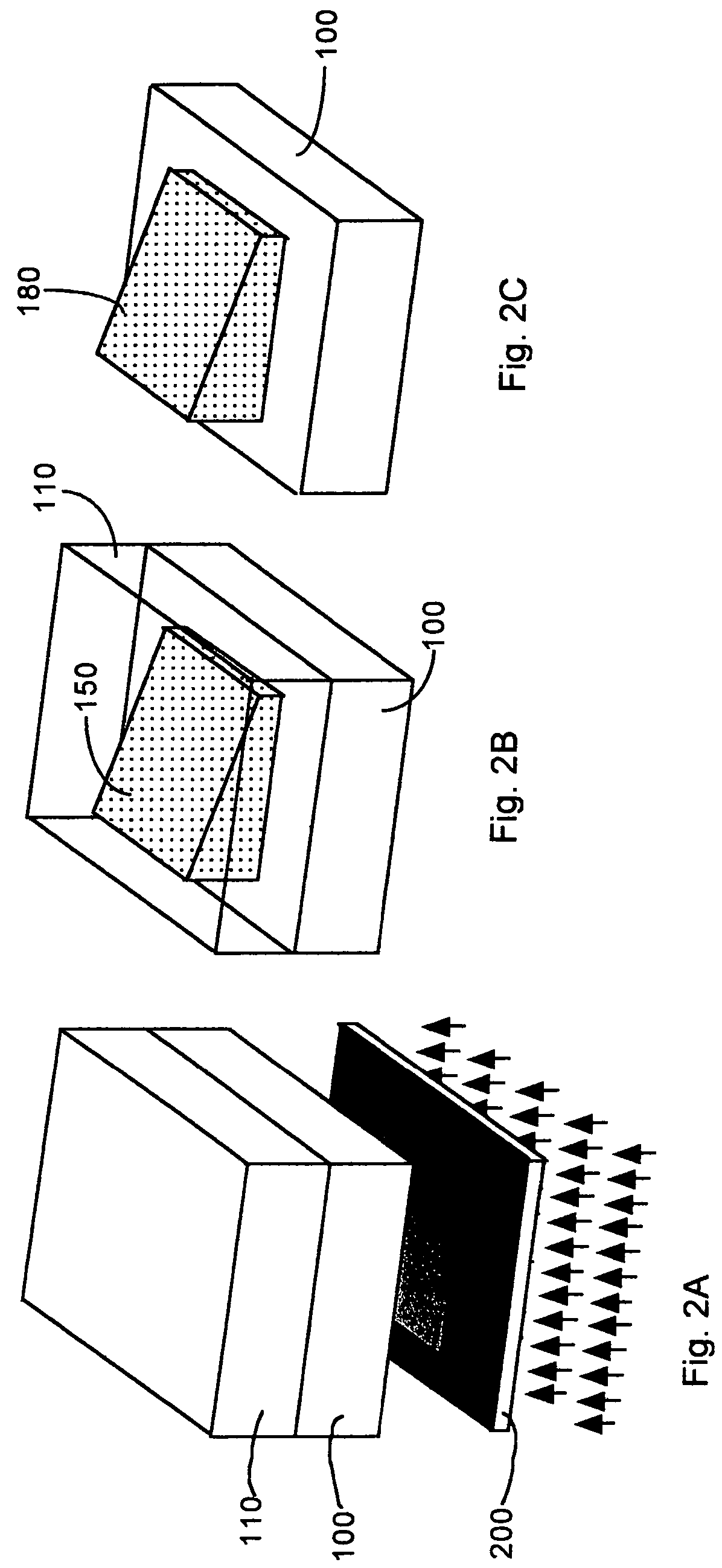
[0027]In one embodiment, the substrate is transparent or essentially transparent to said light. Thus, appropriate substrates include most glasses, fused silica, and a variety of polymers. As said light propagates through said layer, the intensity of said light decreases monotonically due to the absorption of said light by chemical components of said layer. We utilize a known property of photo-sensitized epoxy resists that requires that a minimum exposure dose, which is defined as the product of the intensity of said light times the duration of the exposure, is necessary to polymerize said photo-sensitized epoxy resist. Due to said decrease in said light intensity, the exposure dose also decreases monotonically in the direction of exposure light propagation within said layer. Thus, by suitable selection of impinging UV light intensity and exposure duration, one may cause a portion of said layer to polymerize, wherein said polymerized portion has thickness less than or equal to said initial thickness, and resides adjacent to the substrate. By varying the intensity of said impinging exposing light across the width and breadth of the surface of said substrate, the thickness of the polymerized portion of the layer can be made to vary from zero thickness up to the initial thickness of the layer.

Problems solved by technology

A major limitation results from the fact that the greatest thickness of positive photoresist that may be processed in the manner described above is generally less than 100 μm.
If one attempts to expose too thick a layer, the UV light fails to adequately penetrate the deeper-lying volumes of the positive photoresist.
As a result, the deeper-lying volumes fail to soften, therefore undesirably preventing full-thickness removal of the resist.
With development, the unpolymerized volumes of SU-8 near the photoresist-substrate interface would dissolve, and the entire SU-8 film would undesirably lift off the substrate.

Method used


Image

  • 3-D structures with smoothly-varying topographical features in photo-sensitive epoxy resists
  • 3-D structures with smoothly-varying topographical features in photo-sensitive epoxy resists
  • 3-D structures with smoothly-varying topographical features in photo-sensitive epoxy resists

Examples


Embodiment Construction

[0040]The present invention comprises a new process by which 3-D structures with smoothly-varying topographic features and continuously-varying thickness can be fabricated using one layer of SU-8, one mask, and one exposure and development process sequence. In one embodiment, the substrate is transparent or essentially transparent to the light needed for exposure of the SU-8. Thus, appropriate substrates include most glasses, quartz, and a variety of polymers.

Process Sequence

[0041]The following processing steps may be performed in accordance with one embodiment of the invention:[0042]1. Clean a substrate and apply an adhesion-promoter, if desired and / or necessary.

Subsequent steps may be performed in an orange room.[0043]2. Spin-on or otherwise apply a layer of SU-8 at least as thick as the thickest structure desired. For some applications, the thickness of the applied SU-8 layer may be 10%-20% thicker than the thickness of the thickest structure desired (or possibly even thicker). I...


PUM

PropertyMeasurementUnit
thicknessaaaaaaaaaa
thicknessaaaaaaaaaa
thicknessesaaaaaaaaaa

Abstract

3-D structures which are fabricated by gray-tone exposure of a class of thick negative photo-sensitized epoxy resists from the substrate side of a transparent substrate, using development methods that rely upon a physical distinction between polymerized (solid) and unpolymerized (liquid) photoresist at elevated temperatures Such structures may exhibit smoothly-varying topographic features with thicknesses as great as 2 mm.

Description

PRIOR APPLICATION[0001]This is a division of prior application Ser. No. 09 / 902,029, filed on Jul. 10, 2001 now U.S. Pat. No. 6,485,306, the priority of which is hereby claimed.BACKGROUND OF THE INVENTION[0002]1. Field of the Invention[0003]The present invention relates to techniques for processing photoresist materials generally used in the fabrication of microelectronic, micro-optical and micromechanical devices.[0004]2. Description of the Background Art[0005]Various types of microelectronic, micro-optical, and / or micromechanical structures may exhibit overall dimensions ranging between 50 microns (μm) to a few millimeters (mm). Such structures are useful in creating devices that are purely mechanical (such as watch gears), electro-mechanical (such as electrostatically-driven vibrating elements), optical (such as arrays of lenses), electro-optical (such as movable micro-mirrors), or for use with fluids (such as ink-jet printing heads).[0006]A common method for fabricating such stru...

Claims


Application Information

Patent Timeline
Patent Type & Authority Patents(United States)
IPC IPC(8): G03F7/00G03F7/004G03F7/20G03F7/38G09B11/00
CPCG03F7/2022G09B11/00G03F7/38
Inventor AFROMOWITZ, MARTIN A.
Owner AFROMOWITZ MARTIN A
Learn More