Steam generation function-equipped high-frequency heating device

a high-frequency heating device and function technology, applied in the field of high-frequency heating devices, can solve the problems of difficult daily cleaning of the periphery of the heating chamber, limited cooking variations, unsanitary atmosphere, etc., and achieve the effect of enhancing the close contact between the heater device and the evaporation tray and enhancing the close conta

Inactive Publication Date: 2007-12-04
PANASONIC CORP
View PDF21 Cites 14 Cited by
  • Summary
  • Abstract
  • Description
  • Claims
  • Application Information

AI Technical Summary

Benefits of technology

[0034]With the construction as described above, the speed from dropping of water until the dropped water is evaporated is more remarkably increased even when the same watt value as the conventional device and the prior invention is applied.
[0069]Furthermore, the high frequency heating apparatus having the steam generating function according to the present invention is designed so that particularly the holding plate is designed to have a convex shape in the longitudinal direction of the heater device, whereby the close contact between the heater device and the evaporation tray can be further enhanced.

Problems solved by technology

However, use of only heating based on high frequency heating has such a disadvantage that the cooking variations are limited.
However, the cooking based on the combination of high frequency heating and steam heating needs a labor of carrying out each of the heating treatments separately from each other while transferring heating target foodstuff between respective cooking devices.
According to this publication, a vaporizing chamber for generating heating steam is embedded at the lower side of the heating chamber, and water is supplied from a water tank with keeping a fixed water level at all times. Accordingly, it is difficult to carry out a daily cleaning work of the periphery of the heating chamber, and particularly in the vaporizing chamber, calcium, magnesium, etc. contained in water are condensed in the generating process of steam and precipitate and stick to the bottom portion of the vaporizing chamber and in pipes and thus the occurrence amount of steam is reduced, which causes such an unsanitary atmosphere that mold, etc. are liable to breed.
However, there occur problems of breeding of miscellaneous bacteria in a pipe for introducing steam, breakage caused by freezing, contamination of foreign materials such as rust, etc., and it is frequently difficult to dismantle / clean the heating means.
Therefore, the system of introducing steam from the outside is difficult to be adopted for cooking devices in which sanitation care is needed.
Therefore, it is impossible to accurately measure the temperature of the heating target.
In this case, heating control which is carried out on the basis of the temperature detection result of the infrared sensor is not normally operated, and thus a disadvantage such as insufficient heating, excessive heating or the like occurs.
Particularly when automatic cooking is carried out according to a sequential procedure, the cooking process goes to a next step although heating fails, and the cooking target is irrecoverable by mere re-heating, standing to cool or the like, so that the cooking itself may finally fail.
Furthermore, heating cannot be necessarily performed according to a heating pattern having a high heating efficiency in accordance with the kind of the heating target and each temperature state of frozen articles, refrigerated articles or the like, and thus the heating time is lengthened.
However, the applicant of this application has not yet been satisfied with the above invention, and has sought further increase of the heating efficiency.
However, the reflection plate is bulky and it obstructs the trend of miniaturization, and the applicant considers that this is not used.

Method used


Image

  • Steam generation function-equipped high-frequency heating device
  • Steam generation function-equipped high-frequency heating device
  • Steam generation function-equipped high-frequency heating device

Examples


first embodiment

[0100]In (A1) of FIG. 8 showing the first embodiment, 10 represents the housing of the main body of the apparatus, 11 represents a planar heater device. The planar heater device 11 is achieved by shaping into a plate-like form a heater device in which a U-shaped type sheathed heater is embedded in aluminum die cast, and it is characterized in that the plate-shaped portion is directly fixed to the back side of an iron evaporation tray.

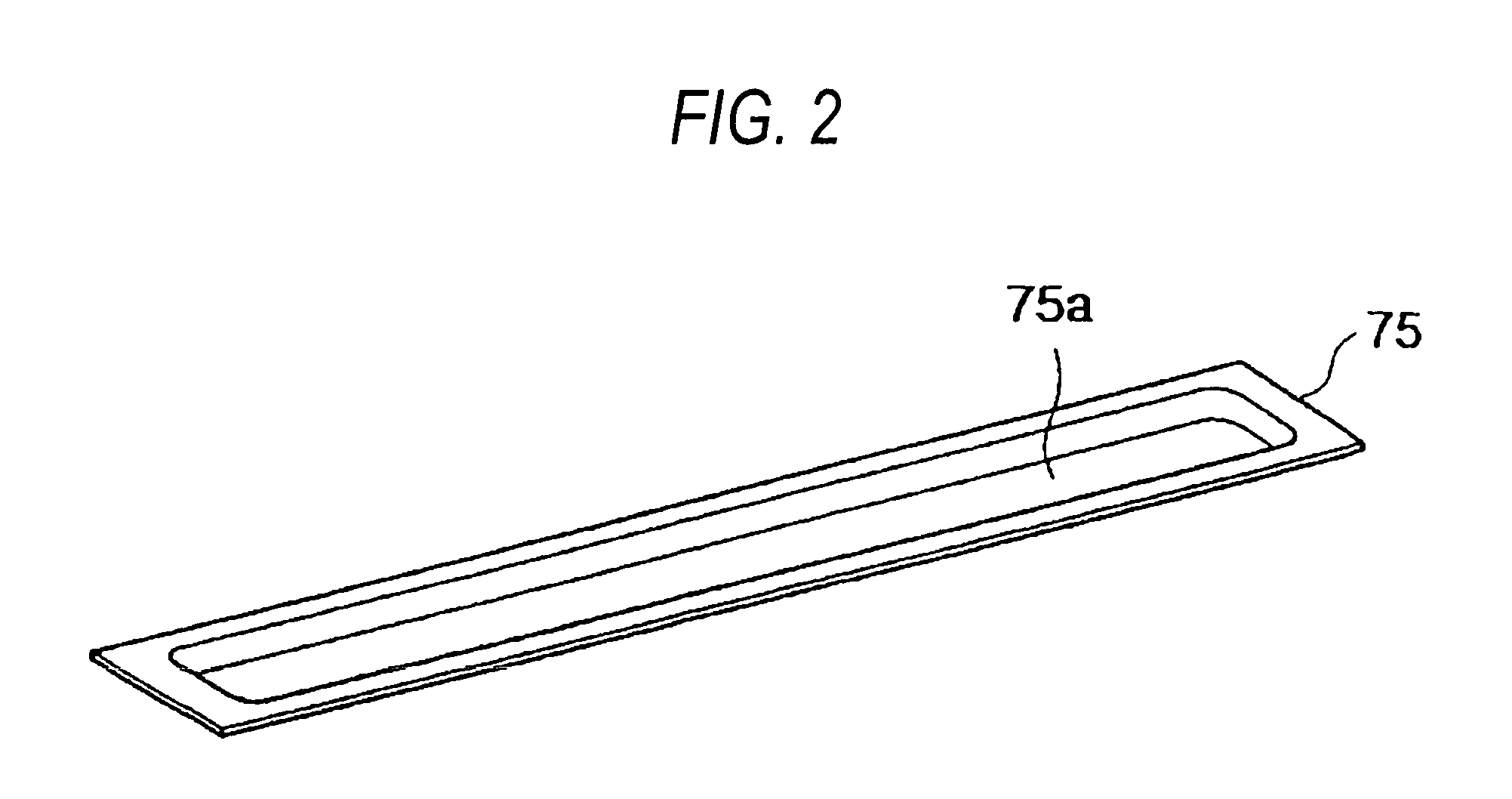
[0101]FIG. 9 is an exploded perspective view showing the planar heater device, (A) is a perspective view showing an evaporation tray, (B) is a perspective view showing a heater device, (B1) is a perspective view of the fixing side to the evaporation tray, and (B2) is a perspective view showing the back side.

[0102]In (A), 20 represents a metal evaporation tray. A tray portion is constructed by the side surface 21 of the tray and the bottom portion 22, and screw holes 23 are formed.

[0103]In (B1), 11 represents a heater device formed of an aluminum die cas...

second embodiment

[0112]In (A2) of FIG. 8 showing the second embodiment, 10 represents the housing of the main body of the apparatus, and 12 represents a deep tray container type heater device. The deep tray container type heater device 12 is characterized in that a heater device in which a sheathed heater is embedded in an aluminum die cast is shaped like a deep tray container, an evaporation tray formed of iron is partially hollowed out and the deep tray container type heater device is fitted in the hollow-out portion.

[0113]FIG. 10 is an exploded perspective view showing the deep tray container type heater device, wherein (A) is a perspective view showing a metal plate from which an evaporation tray portion is hollowed out, (B) is a perspective view showing the heater device, (B1) is a perspective view showing the fixing side to the metal plate, and (B2) is a perspective view showing the back side.

[0114]In (A), 30 represents an evaporation tray support plate provided with a hollow-out portion 31 ac...

third embodiment

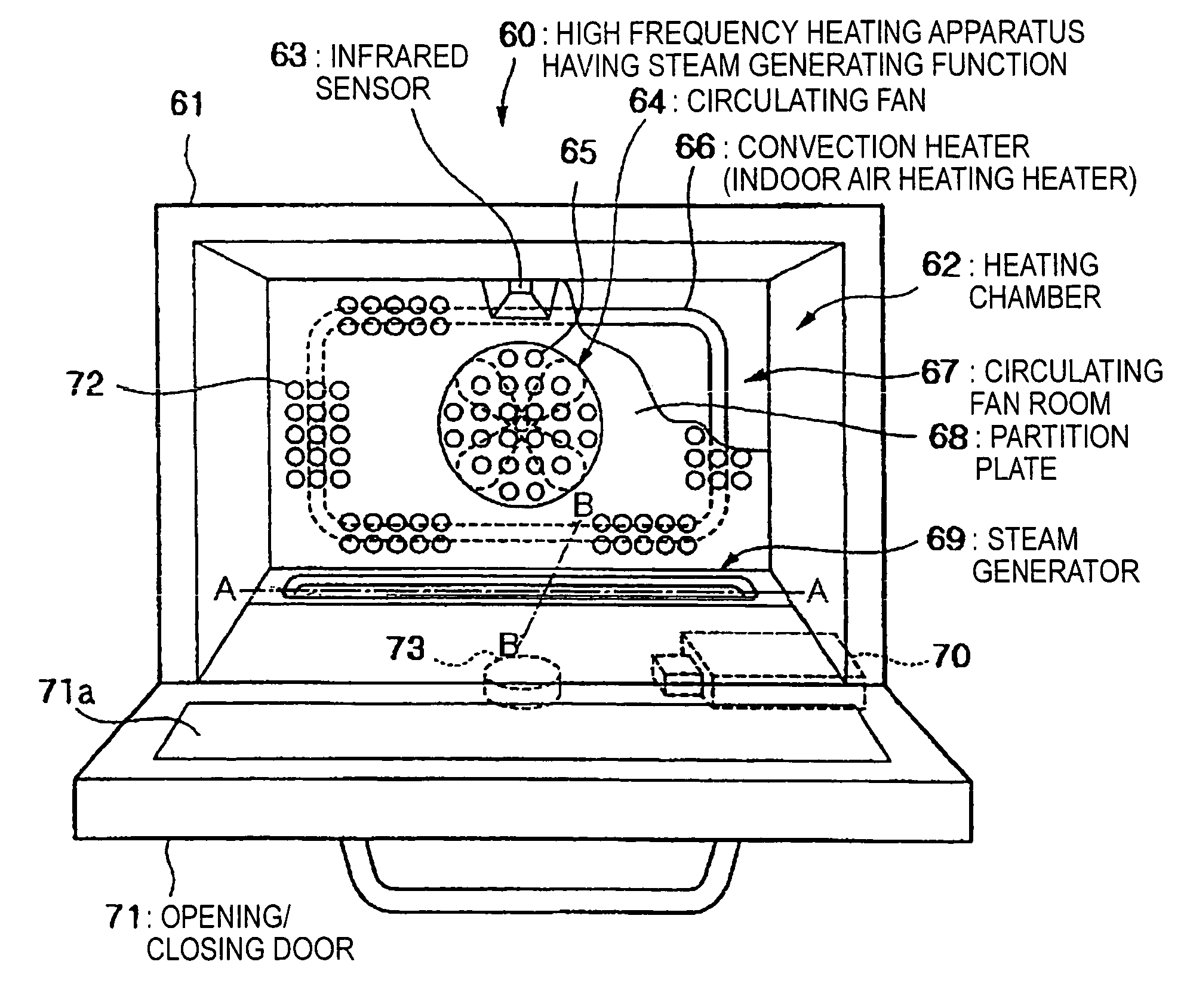
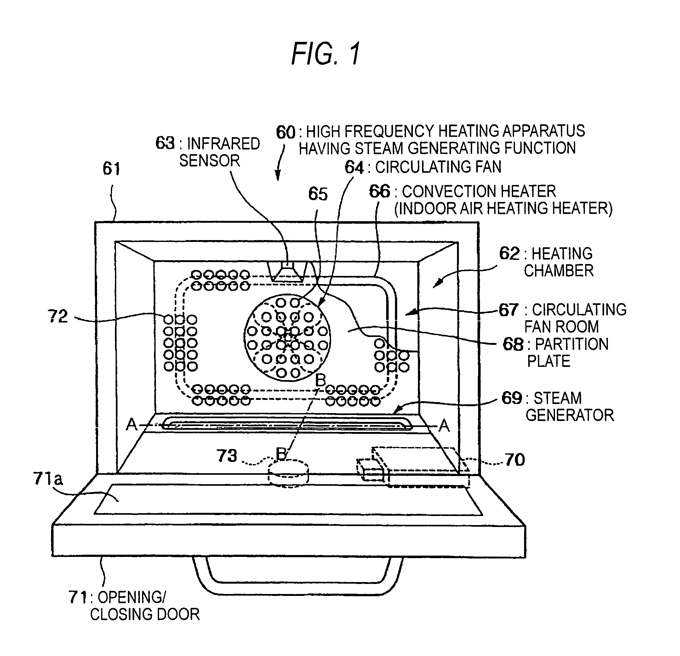
[0122]FIG. 11 is a diagram showing the location places and number of evaporation trays in the high frequency heating apparatus according to the present invention, wherein (a) is a front view showing the state that the opening / closing door of the high frequency heating apparatus is opened, and (b) is a front view showing the positions of the evaporation trays.

[0123]In 8a), 40 represents a high frequency heating apparatus having a steam generating function, 41 represents an upper ceiling in the heating chamber, 42 represents a right side wall, 43 represents a left side wall, 44 represents the bottom surface, 45 represents a metal plate having an evaporation tray, 46R represents a right evaporation tray, 46L represents a left evaporation tray, 47R represents a right water supply port, 47L represents a left water supply port and 49 represents a circulating fan.

[0124]As described above, the evaporation tray 46 according to the present invention has large evaporation capability, and thus ...


PUM

PropertyMeasurementUnit
timeaaaaaaaaaa
timeaaaaaaaaaa
heightaaaaaaaaaa

Abstract

An object of the present invention is to provide a high frequency heating apparatus having a steam generating function in which a time required for evaporation of dropped water can be remarkably increased when water is dropped onto an evaporation tray and the heating efficiency is high.The high frequency heating apparatus has a steam generating function that includes a high frequency generator and a steam generator that includes an evaporation tray provided on the bottom surface of a heating chamber in which a heating target is mounted and a heater device for heating the evaporation tray to generate steam in the heating chamber, wherein the heater device is constructed as a heater device (11) having a sheathed heater (113) embedded in an aluminum die cast (111), and the heater device is directly attached to the back side of the evaporation tray (22).

Description

TECHNICAL FIELD[0001]The present invention relates to a high frequency heating apparatus having a steam generating function for carrying out a heating treatment on a heating target by combining high frequency heating and steam heating, and particularly to steam heating thereofBACKGROUND ART[0002]A high frequency heating apparatus having high frequency generating means for outputting high frequency waves to the inside of a heating chamber in which a heating target is accommodated has rapidly propagated as a microwave oven serving as cooking equipment for foodstuff, etc. because it can efficiently heat a heating target in a heating chamber in a short time. However, use of only heating based on high frequency heating has such a disadvantage that the cooking variations are limited.[0003]Therefore, as conventional high frequency heating apparatuses have been provided a microwave oven having a high frequency wave generating apparatus for heating, a combination cooking range added with a c...

Claims


Application Information

Patent Timeline
Patent Type & Authority Patents(United States)
IPC IPC(8): H05B6/80F24C15/00
CPCH05B6/6479F24C15/327
Inventor KANZAKI, KOUJIHAYAKAWA, YUJIYAMASAKI, TAKAHIKOMORI, YASUHISAAKASHI, TAKAYUKIKAWAI, HIROSHI
Owner PANASONIC CORP
Why Eureka
Try Eureka