Optical tunable filter and method of manufacturing the same
a technology of optical tunable filters and manufacturing methods, applied in waveguide devices, instruments, optical elements, etc., can solve the problems of movable parts, drive electrodes can stick, and the driving becomes unstable, so as to simplify the manufacturing process of the first substrate
- Summary
- Abstract
- Description
- Claims
- Application Information
AI Technical Summary
Benefits of technology
Problems solved by technology
Method used
Image
Examples
first embodiment
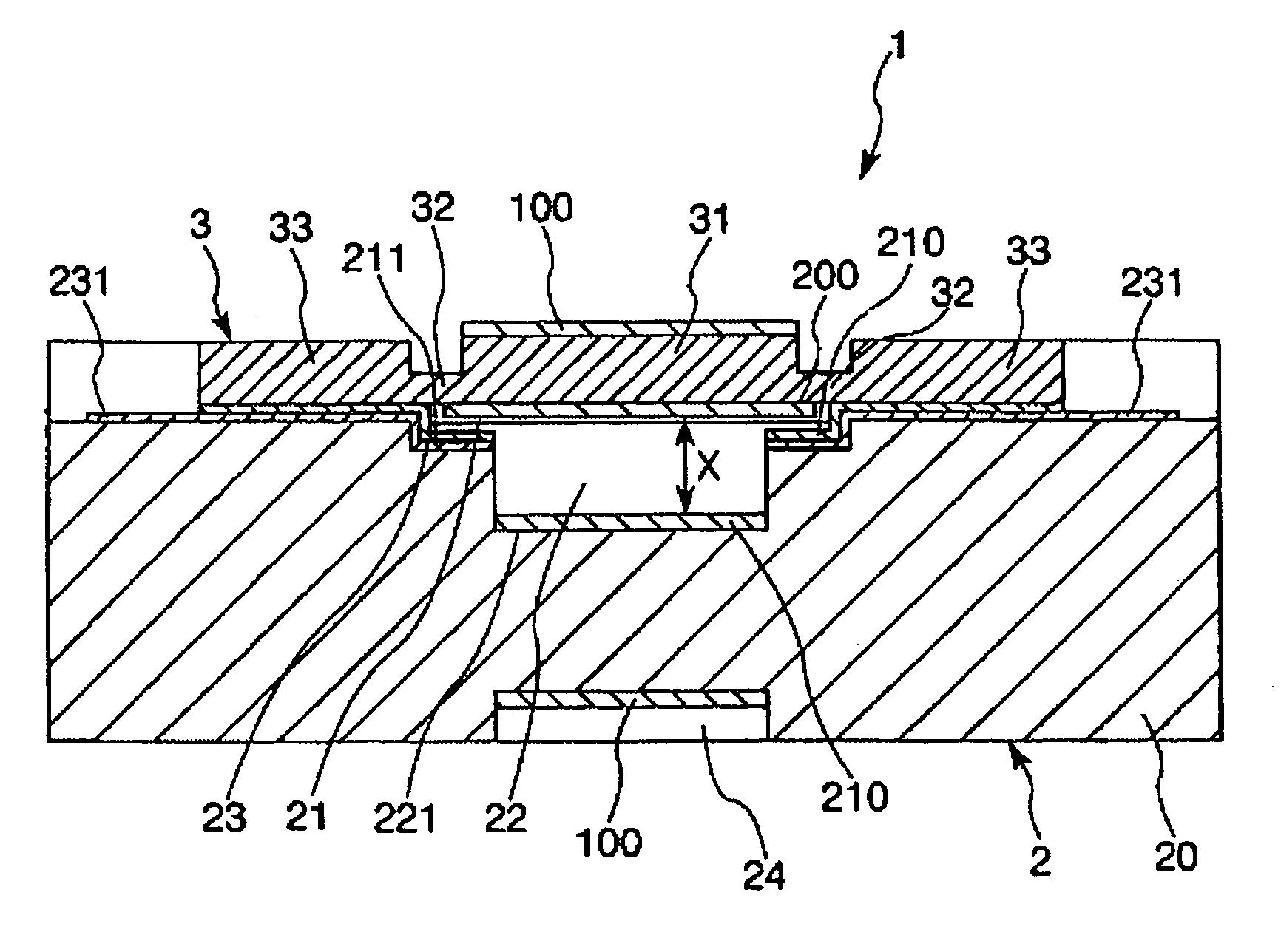
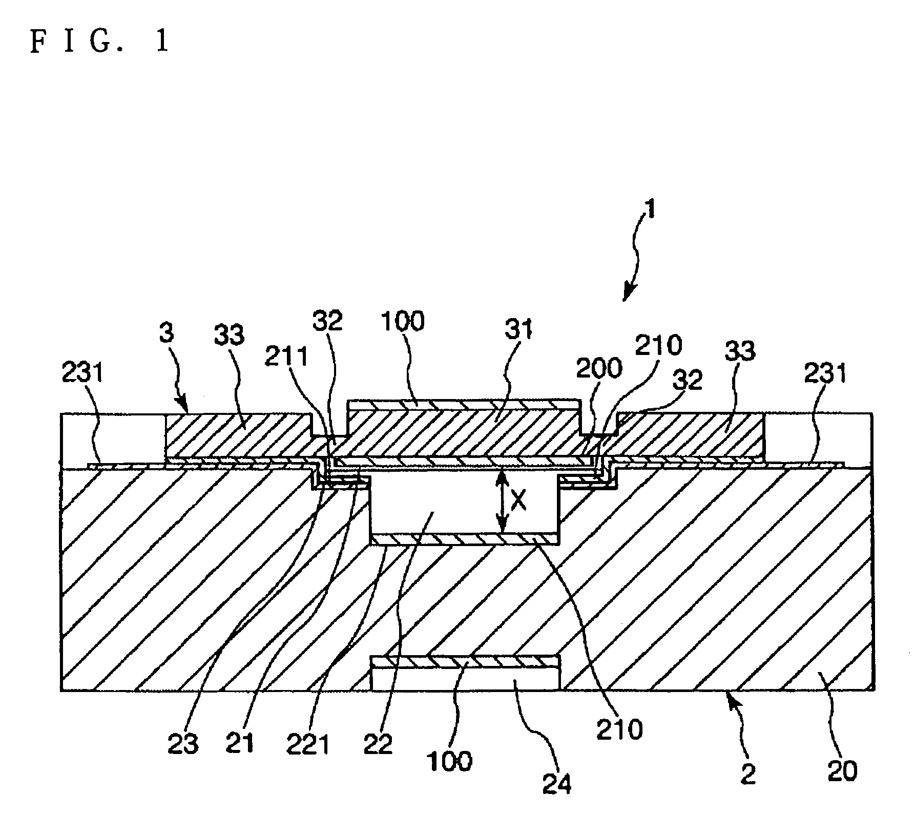
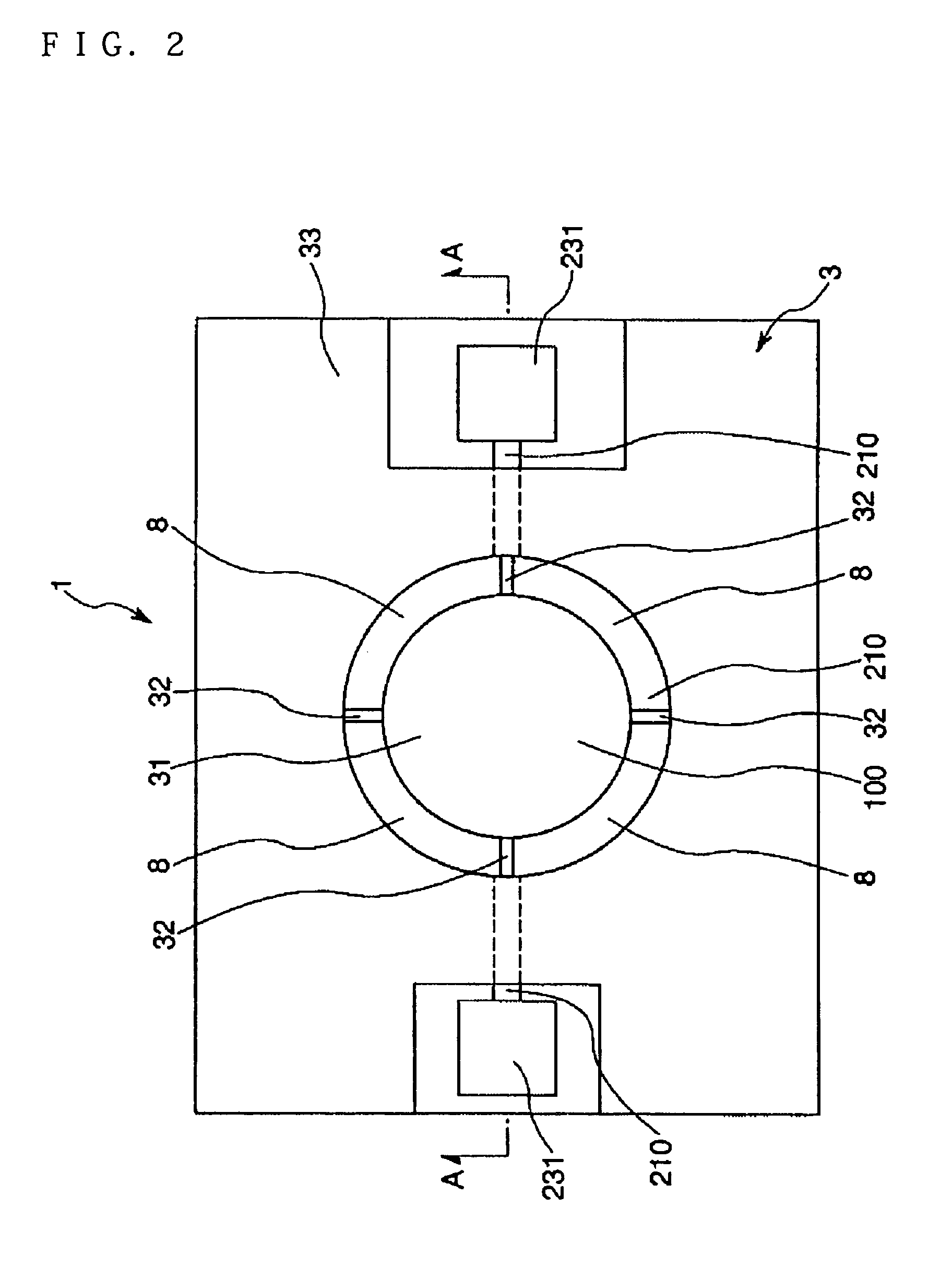
[0074]FIG. 1 is a sectional view of an optical tunable filter of a first embodiment along the line A-A of FIG. 2. FIG. 2 is a plan view of the optical tunable filter shown in FIG. 1. In the following description, the upper side of FIG. 1 is called “upward” and the lower side of FIG. 1 is called “downward”.
[0075]As shown in FIG. 1, an optical tunable filter 1 includes a first substrate 3 that is made of silicon, a base substrate 2 that is opposed to the first substrate 3, a first gap 21 and a second gap 22 that are provided between the first substrate 3 and the base substrate 2.
[0076]The first substrate 3 has conducting and light transmission properties. The first substrate 3 has a movable part 31 that is positioned in the middle, a supporting member 32 that supports the movable part 31 in a displaceable (movable) state and a conducting part 33 that turns on electricity to the movable part 31.
[0077]The movable part 31, the supporting member 32 and the conducting part 33 are formed so...
second embodiment
[0193]As shown in FIG. 7, in the optical tunable filter 1 of the second embodiment, an upper side (opposite side to the base substrate 2 side) of the movable part 31 and the conducting part 33 are coupled to the supporting member 32.
[0194]A manufacturing method is described below.
[0195]Manufacturing Method
[0196]FIGS. 8a and 8b are figures for explaining the manufacturing method of the second embodiment (schematically showing manufacturing processes). A feature of the manufacturing method according to the second embodiment is that the supporting member is made thin by processing from a lower side of the supporting member (a counter face side relative to the second base substrate 2 of the second Si layer 73). The manufacturing processes are the same as those of the first embodiment except process ′ is added after process in step (2) and process in step (4) is different. Process ′ in step (2) and process in step (4) are now described.
[0197]′ A photoresist pattern (not shown in the f...
third embodiment
[0202]As shown in FIG. 9, in the optical tunable filter 1 of the third embodiment, a center location of the movable part 31 and the conducting part 33 are coupled to the supporting member 32. A manufacturing method is described below.
[0203]Manufacturing Method
[0204]FIGS. 10a and 10b are figures for explaining the manufacturing method of the third embodiment (schematically showing manufacturing processes). A feature of the manufacturing method according to the third embodiment is that the supporting member is made thin by processing from the upper side and the lower side of the supporting member. The manufacturing processes are the same as those of the first embodiment except process ″ is added after process in step (2) and process in step (4) is different.
[0205]Process ″ in step (2) and process in step (4) are now described.
[0206]″ A photoresist pattern (not shown in the figures) is formed on the undersurface of the second Si layer 73 by photolithography and two-tiered anisotropi...
PUM
| Property | Measurement | Unit |
|---|---|---|
| angles | aaaaa | aaaaa |
| total thickness | aaaaa | aaaaa |
| thickness | aaaaa | aaaaa |
Abstract
Description
Claims
Application Information
 - R&D
- Intellectual Property
- Life Sciences
- Materials
- Tech Scout
- Unparalleled Data Quality
- Higher Quality Content
- 60% Fewer Hallucinations
Browse by: Latest US Patents, China's latest patents, Technical Efficacy Thesaurus, Application Domain, Technology Topic, Popular Technical Reports.
© 2025 PatSnap. All rights reserved.Legal|Privacy policy|Modern Slavery Act Transparency Statement|Sitemap|About US| Contact US: help@patsnap.com


