
Prediction and assessment of ablation of cardiac tissue

Active Publication Date: 2007-12-11
BIOSENSE WEBSTER INC
View PDF20 Cites 233 Cited by
  • Summary
  • Abstract
  • Description
  • Claims
  • Application Information

AI Technical Summary

Benefits of technology

[0008]Embodiments of the present invention provide methods and apparatus for use in ablating body tissue, and particularly heart tissue. These embodiments are based on a probe, such as a catheter, having an ablation electrode at its tip, and comprising a position and orientation sensor. The sensor is used to continuously measure the position and orientation of the probe, and thus provides an accurate measurement of the angle and penetration depth of the probe tip relative to the tissue that is to be ablated.
[0009]The measured angle and penetration depth are used in predicting the extent of ablation of the tissue that expected for a given dosage of radiation applied by the catheter in this position. Because the probe permits the angle and penetration depth to be measured directly, rather than relying on secondary indicators such as impedance, it enables more accurate prediction of the extent of the ablation region than is possible in systems known in the art. Optionally, the probe may be configured to make other relevant measurements, such as impedance, temperature, tissue characteristics and flow, in order to refine the prediction.
[0010]In some embodiments of the present invention, the probe comprises a cardiac catheter, which is employed, prior to ablating the tissue, to create a map of the interior of the heart, as described in the above-mentioned parent application (U.S. Ser. No. 10 / 277,079). The position sensor readings are then used to determine the position and orientation of the catheter relative to the tissue on the basis of this map. The predicted extent of ablation is displayed on a graphical representation of the map, so that the operator of the catheter can visualize the region that will be ablated and can adjust the RF dosage up or down to enlarge or reduce the region.
[0011]After applying the selected dosage, the catheter is used to measure the actual extent of the ablation, using ultrasonic imaging, for example. The actual, measured extent of the ablation is displayed on the map, typically superimposed for comparison on the predicted extent of ablation. The operator can use this visual comparison to plan and adjust the RF dosage that will be administered in subsequent ablation steps at the same site or other sites in the heart. Additionally or alternatively, the catheter console, which performs the above-mentioned mapping and prediction functions, may use the comparison of predicted and actual results to adaptively improve the accuracy of prediction in subsequent ablation steps.

Problems solved by technology

When this sort of procedure is successful, it creates non-conducting lesions in the cardiac tissue, which disrupt the abnormal electrical pathway causing the arrhythmia.
It is often difficult to determine the proper dosage of RF energy that should be applied in an ablation procedure in order to achieve the desired result.
When the dosage is insufficient, the non-conducting lesion will not extend deeply enough through the heart wall to disrupt the abnormal conduction, so that arrhythmia may persist or return after the procedure is completed.
On the other hand, excessive RF dosage may cause dangerous damage to the tissue at and around the ablation site.
These qualities, however, are difficult to ascertain in catheterization systems known in the art, and they may vary during the ablation procedure.

Method used


Image

  • Prediction and assessment of ablation of cardiac tissue
  • Prediction and assessment of ablation of cardiac tissue
  • Prediction and assessment of ablation of cardiac tissue

Examples


Embodiment Construction

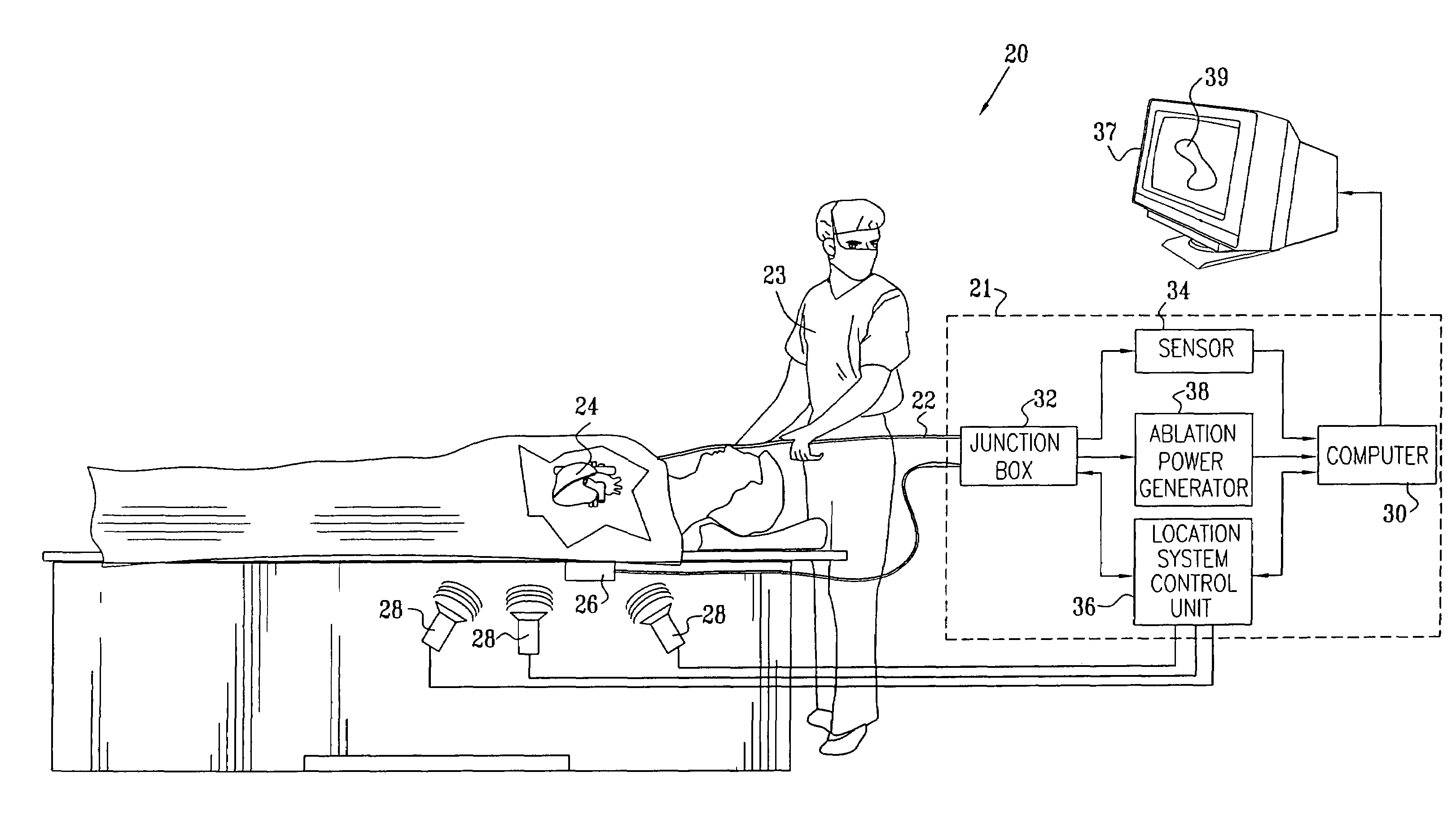
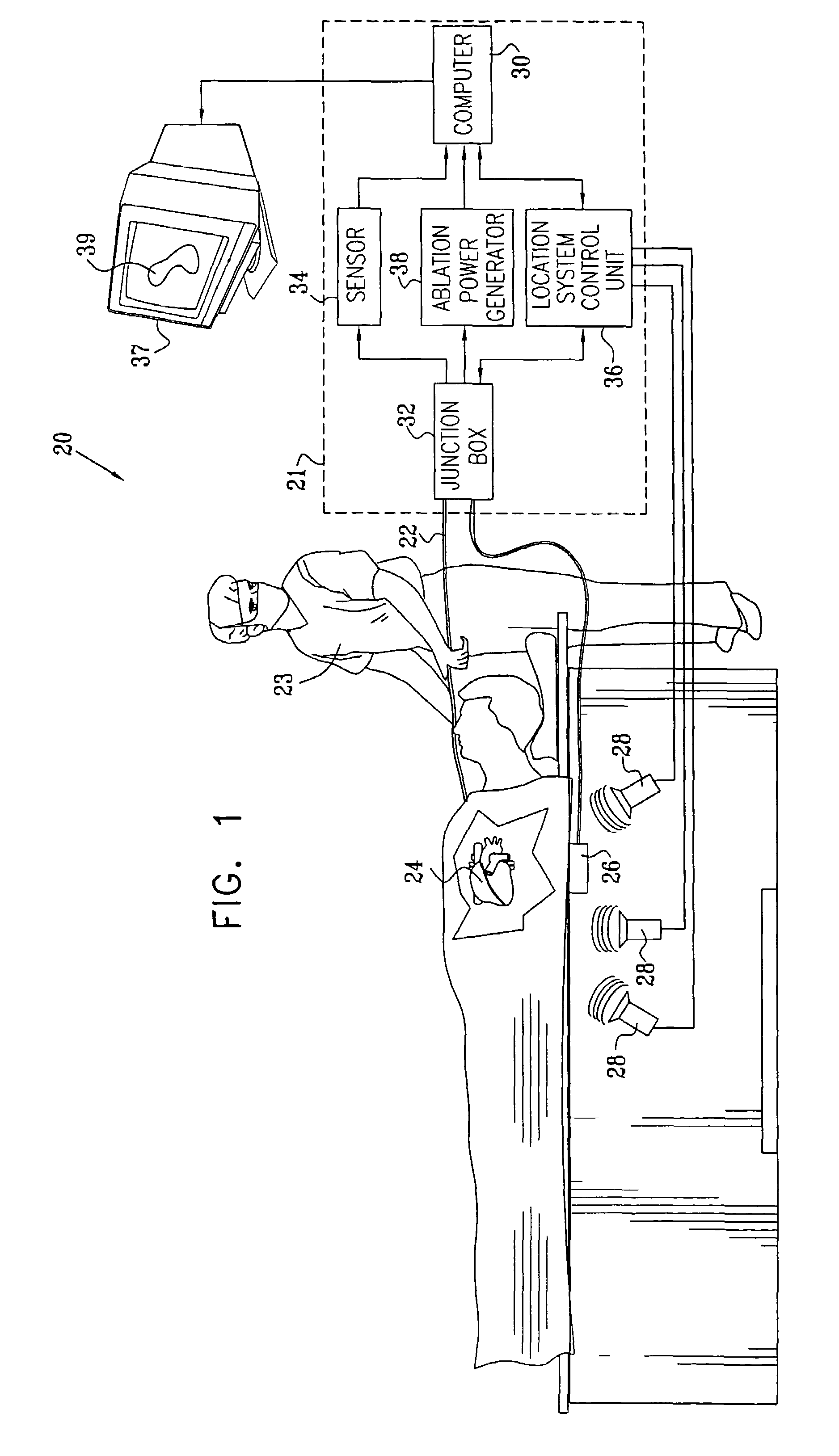
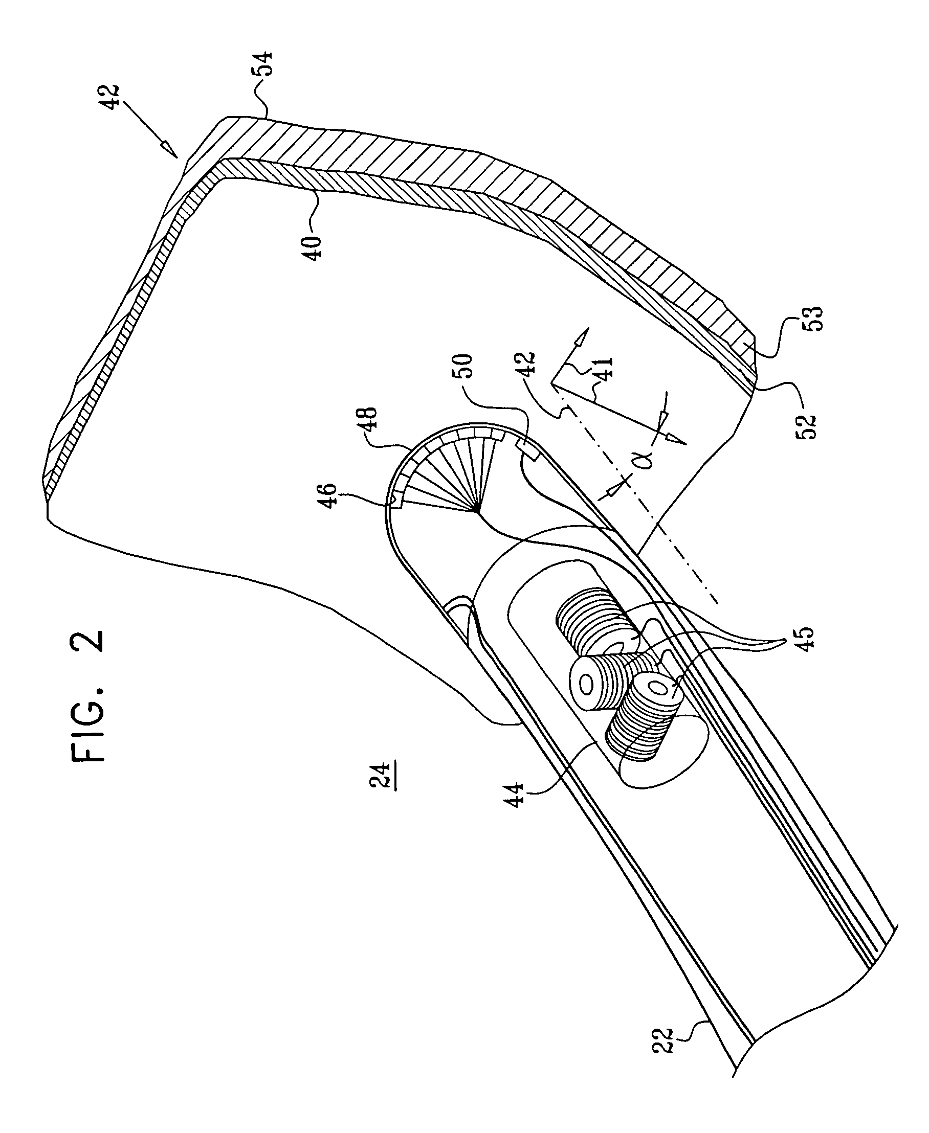
[0051]FIG. 1 is a schematic, pictorial illustration of a system 20 for cardiac ablation treatment in a heart 24 of a subject, in accordance with an embodiment of the present invention. System 20 comprises an elongate invasive probe, typically a catheter 22, which is inserted by an operator 23 through a vein or artery of the subject into a chamber of the heart. The catheter comprises, at its distal end, a position sensor, at least one ablation element, such as an ablation electrode, and, typically, one or more additional physiological sensors, as described below with reference to FIG. 2.

[0052]Catheter22 is connected to and controlled by a console 21, which typically comprises a location system control unit 36, an ablation power generator 38 and a sensor monitoring and control unit 34. These elements are connected to the proximal end of catheter 22 via a junction box 32. Junction box 32 routes (a) conducting wires and temperature sensor signals from catheter 22 to ablation power gener...


PUM


Abstract

A method for ablating tissue in an organ inside a body of a subject includes bringing a probe inside the body into a position in contact with the tissue to be ablated, and measuring one or more local parameters at the position using the probe prior to ablating the tissue. A map of the organ is displayed, showing, based on the one or more local parameters, a predicted extent of ablation of the tissue to be achieved for a given dosage of energy applied at the position using the probe. The given dosage of energy is applied to ablate the tissue using the probe, and an actual extent of the ablation at the position is measured using the probe subsequent to ablating the tissue. The measured actual extent of the ablation is displayed on the map for comparison with the predicted extent.

Description

CROSS-REFERENCE TO RELATED APPLICATION[0001]This application is a continuation-in-part of U.S. patent application No. 10 / 277,079, filed Oct. 21, 2002, now U.S. Pat. No. 7,001,383 which is assigned to the assignee of the present patent application and whose disclosure is incorporated herein by reference.FIELD OF THE INVENTION[0002]The present invention relates generally to minimally-invasive treatment of organs inside the body, and specifically to methods and devices for prediction and assessment of ablation treatments applied to cardiac tissue.BACKGROUND OF THE INVENTION[0003]Radio frequency (RF) ablation is widely used for treating cardiac arrhythmias. RF ablation is commonly carried out by inserting a catheter through the patient's vascular system into the heart, and bringing the distal tip of the catheter into contact with the cardiac tissue at the site that is to be ablated. RF electrical current is then conducted through wires in the catheter to one or more electrodes at the ti...

Claims


Application Information

Patent Timeline
IPC IPC(8): A61B18/18A61B5/06A61B19/00A61B8/06A61B8/12A61B17/00A61B17/32A61B18/00A61B18/04A61B18/12A61B18/14A61B18/24A61N1/06
CPCA61B5/06A61B8/12A61B18/1492A61B19/5244A61B8/445A61B8/4461A61B18/24A61B19/56A61B2017/00026A61B2017/00053A61B2017/00084A61B2017/00106A61B2017/00243A61B2017/00274A61B2018/00351A61B2018/00547A61B2018/00839A61B2019/444A61B2019/502A61B2019/505A61B2019/507A61B2019/5251A61B2019/5272A61B2019/5276A61B2019/528A61B2019/5475A61B2019/504A61B8/06A61B2034/102A61B2034/104A61B2034/2072A61B2090/3975A61B34/20A61B34/25A61B2090/3784A61B90/92A61B2034/105A61B2034/107A61B2034/2051A61B2090/378A61B5/062A61B17/32
Inventor KEIDAR, YARONGOVARI, ASSAFSCHWARTZ, YITZHACK
Owner BIOSENSE WEBSTER INC
Learn More