Low-cost one-dimensional electromagnetic band gap waveguide phase shifter based ESA horn antenna

a phase shifter and one-dimensional electromagnetic technology, applied in the field of one-dimensional electromagnetic band gap waveguide phase shifter based electronically scanned array (esa) horn antenna, can solve the problems of reducing the esa phase shifter count and beam steering computer, exceeding the recurring cost requirements of the above-mentioned system

Active Publication Date: 2007-12-11
ROCKWELL COLLINS INC
View PDF23 Cites 286 Cited by
  • Summary
  • Abstract
  • Description
  • Claims
  • Application Information

AI Technical Summary

Benefits of technology

[0018]It is an advantage of the present invention to utilize electromagnetic band gap phase shifters to provide high-performance analog phase shifting.
[0019]It is an advantage of the present invention to utilize a horn to set gain and beamwidth in an off-scan plane.
[0020]It is a feature of the present invention to provide a dual-mode phase shifter capability in a one-dimensional ESA horn antenna.

Problems solved by technology

One of the major challenges in phased array design is to provide a cost effective and environmentally robust interconnect and construction scheme for the phased array assembly.
Frequently the above-mentioned systems have extremely aggressive recurring cost requirements.
One-dimensional beam scanning significantly reduces the ESA phase shifter count and beam steering computer / interconnect complexity, all which directly contribute to cost.

Method used


Image

  • Low-cost one-dimensional electromagnetic band gap waveguide phase shifter based ESA horn antenna
  • Low-cost one-dimensional electromagnetic band gap waveguide phase shifter based ESA horn antenna
  • Low-cost one-dimensional electromagnetic band gap waveguide phase shifter based ESA horn antenna

Examples


Embodiment Construction

[0034]The present invention is for a low-cost one-dimensional electromagnetic band gap (EBG) waveguide phase shifter based electronically scanned array (ESA) horn antenna.

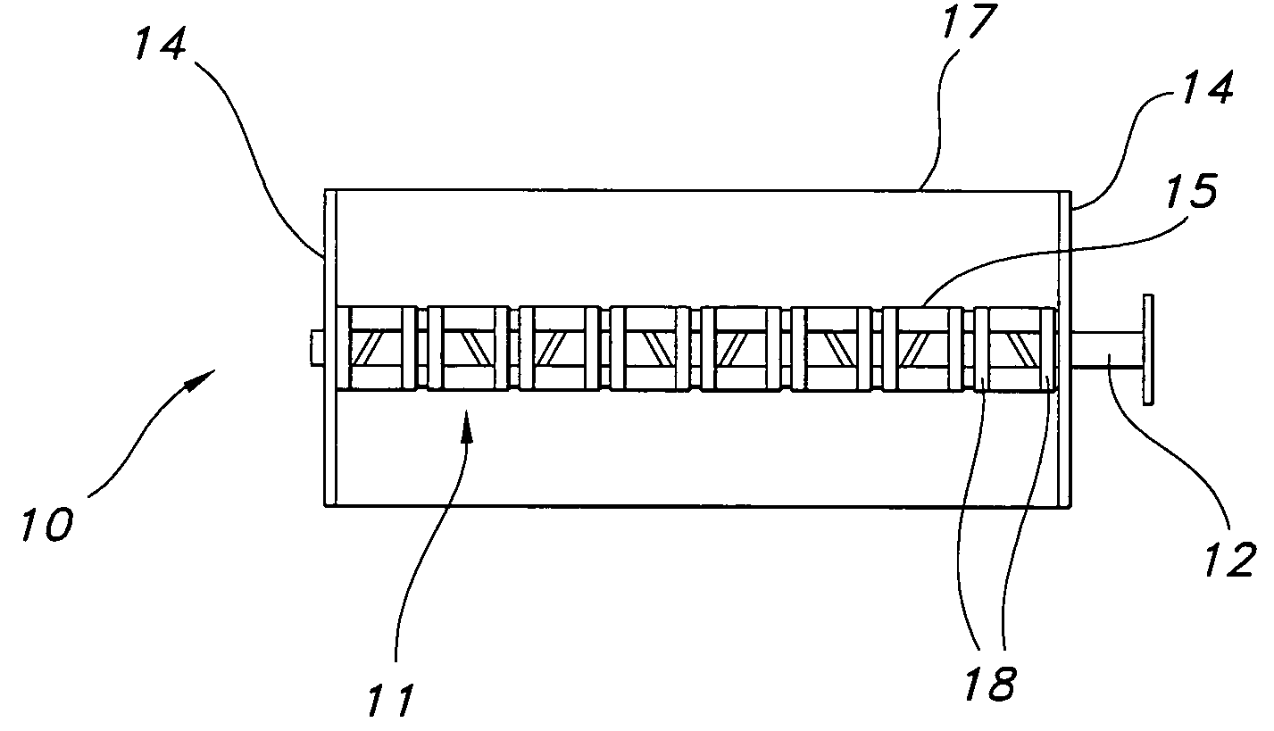
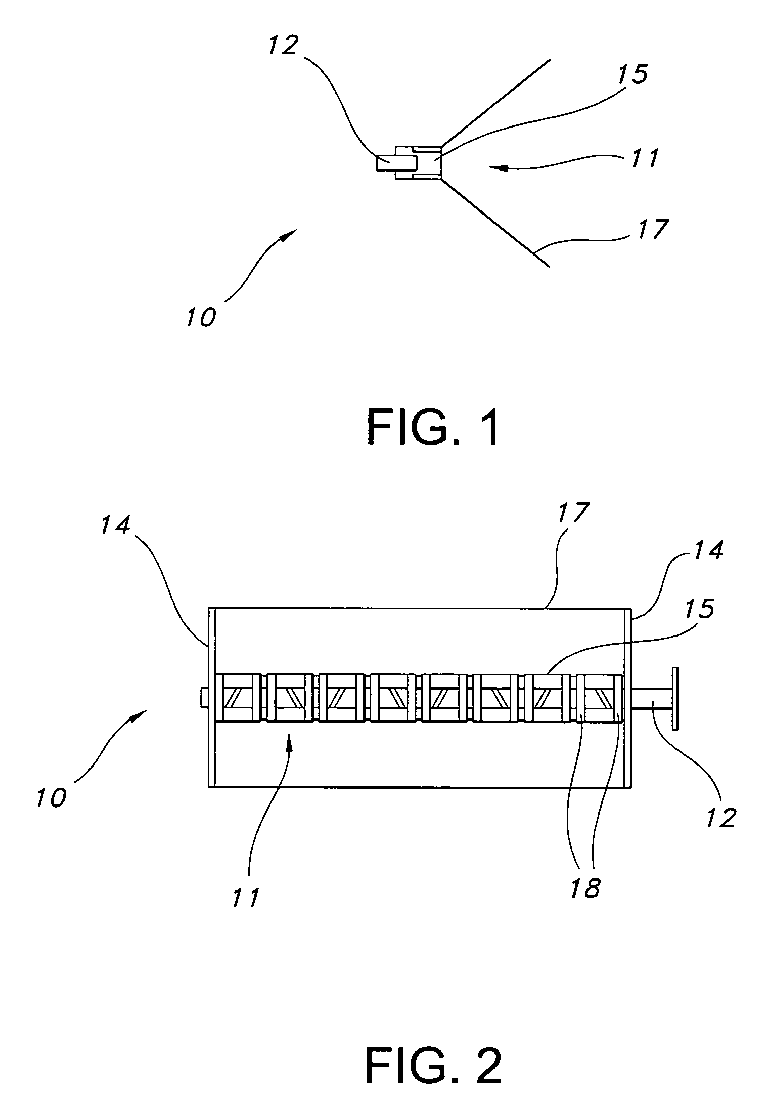
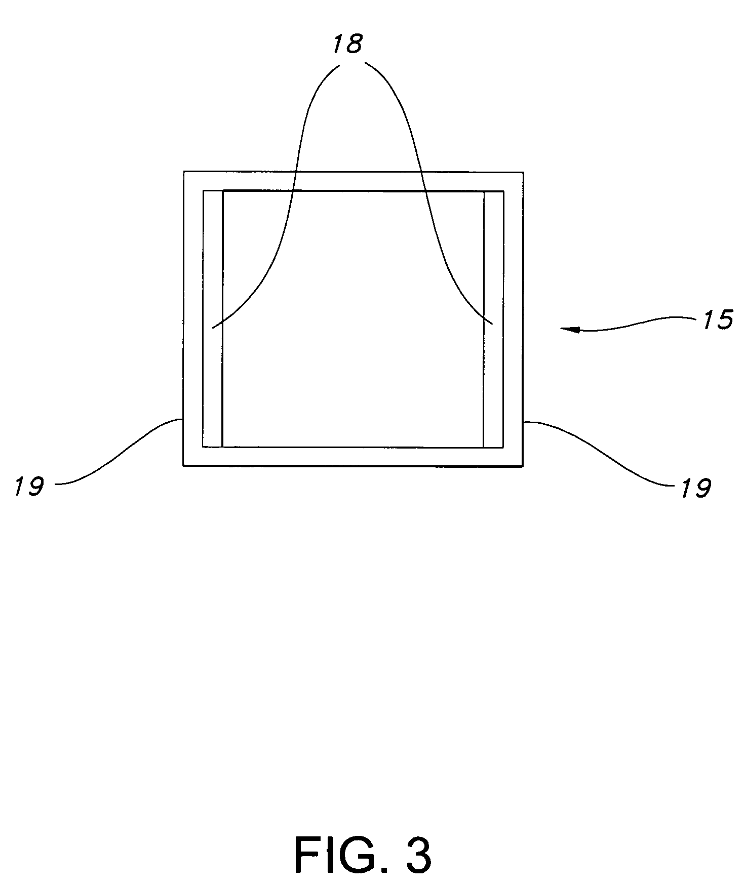
[0035]FIG. 1 illustrates a side view of a linearly polarized one-dimensional ESA horn antenna 10 with EBG waveguide phase shifters 15 of the present invention. A horn 17 is fed by a one-dimensional EBG waveguide phase shifting ESA linear array horn feed 11. The horn 17 may be a metallic sectoral horn. A linear array feed 12 feeds a linear array of EBG waveguide radiating elements 15 that comprise the EBG ESA feed 11. A beam is formed in the plane of the electronic scan by the linear array feed 12. The beam in the orthogonal plane is collimated by the optical characteristics of the horn 17. FIG. 2 is a front view of the horn antenna 10 of the present invention. The horn 17 may be a pyramidal horn with sidewalls 14. The pyramidal horn 17 can operate either in a TE01 or TEM mode, depending on the boundary conditions o...


PUM


Abstract

A one-dimensional electromagnetic band gap (EBG) waveguide phase shifter electronically scanned array (ESA) horn antenna utilizes a linear array of EBG waveguide phase shifters for scanning and radiating a beam. A linear array feed feeds the linear array of EBG waveguide phase shifters. A horn directs radiation from the linear array of EBG waveguide phase shifters. Each of the EBG waveguide phase shifters is a waveguide with vertical and horizontal sidewalls. EBG devices are located on the vertical waveguide walls to shift phase to scan the beam.

Description

CROSS REFERENCE TO RELATED APPLICATIONS[0001]The present application is related to co-pending application Ser. No. 10 / 458,481 filed on Jun. 10, 2003 entitled “One-Dimensional and Two-Dimensional Electronically Scanned Slotted Waveguide Antennas Using Tunable Band Gap Surfaces”; Ser. No. 10 / 354,280 filed on Jan. 30, 2003 entitled “Frequency Agile Material-Based Reflectarray Antenna” invented by James B. West; Ser. No. 10 / 273,459 filed on Oct. 18, 2002 entitled “A Method and Structure for Phased Array Antenna Interconnect” invented by John C. Mather, Christina M. Conway, and James B. West; Ser. No. 10 / 273,872 entitled “A Construction Approach for an EMXT-Based Phased Array Antenna” invented by John C. Mather, Christina M. Conway, James B. West, Gary E. Lehtola, and Joel M. Wichgers; Ser. No. 10 / 698,774 filed on Oct. 23, 2003 entitled “Independently Controlled Dual-Mode Analog Waveguide Phase Shifter” invented by James B. West and Jonathan P. Doane; and Ser. No. 10 / 699,514 filed on Oct...

Claims


Application Information

Patent Timeline
Patent Type & Authority Patents(United States)
IPC IPC(8): H01Q13/00
CPCH01Q13/00H01Q3/2658
Inventor WEST, JAMES B.
Owner ROCKWELL COLLINS INC
Why Eureka
Try Eureka