Ultrathin lens arrays for viewing interlaced images

a technology of interlaced images and lens arrays, which is applied in the field of ultrathin lens arrays, can solve the problems of increasing the frequency of the lenticules in the array, and reducing the thickness of the lens or the lens array

Inactive Publication Date: 2007-12-11
GENIE LENS TECH
View PDF22 Cites 23 Cited by
  • Summary
  • Abstract
  • Description
  • Claims
  • Application Information

AI Technical Summary

Benefits of technology

[0011]The present invention addresses the above problems by lens substrates or arrays formed with numerous lens microstructures or lens sets. Each of these lens microstructures can be used to provide the functionality of a much thicker lenticule or lens of conventional lenticular material as each of the lens microstructures is paired to a set of interlaced image elements or slices, which may be printed digitally, printed with offset printing, printed using web printing, or the like. The lenses of the lens microstructure are each used to focus onto or from a small subset of the slices in a paired set rather than focusing on all of the slices of the set as is required of a lenticule in conventional lenticular technology. Further, the lenses of the lens set or microstructure are each uniquely configured (e.g., with a differing cross sectional shape) to provide its own main viewing direction or focus line / direction such that each lens in a lens microstructure displays the small subset of images (e.g., 1 to 3 images) to which it is mapped and with a lens-specific viewing angle or angular distribution. In practice, the lens microstructures have an overall viewing angle that is generally the combination of the angular distribution of each lens of the lens microstructure with the focus lines or directions of each lens selected such that only select ones of the image elements or slices are displayed or visible as a viewer's line of sight moves through the overall viewing angle. The lens arrays may be significantly thinner than possible or practical with convention lenticular material (e.g., 50 to 90 percent or more reduction in lens thickness), which allows the “paper thin” arrays to be applied to or provided integrally in numerous product surfaces such as in printed labels, attached decals or labels, book jackets, magazine covers, wraparound labels, and many other print and packaging applications.
[0013]With lens arrays using the lens microstructures or lens sets of the invention, the lens microstructures can be configured so as to provide the function provided by a thick conventional lenticule by using a number of thin lenses that are individually configured to focus on a subset of image slices (such as 1 to 3 slices rather than a whole set of 4 to 12 or more slices). The lens arrays can be imprinted with the lens microstructures on a thin film at a very high rate of speed. In one example, a high quality image display assembly is achieved with a 3-mil thick lens array having lens sets or microstructures on one side provided at 40 lens sets per inch (LPI) and an interlaced image on the other side. The interlaced image can be printed rapidly such as at up to 2,000 feet per minute or faster on a web press or similar device. To achieve a similar display capability with a conventional lenticular lens array may require a frequency of 40 LPI and a thickness of about 80 mils or more. From these few example, it can be seen that the use of lens microstructures to generate a lens array provides a significant decrease in material costs, allows very thin lens arrays or substrates to be used in numerous applications for which conventional lenticular material is not practical, and greatly simplifies manufacturing by, for example, allowing printing of interlaced images at lower frequency or fineness.

Problems solved by technology

An ongoing problem with traditional lenticular lens material used to focus on and magnify printed interlaced images is that the lens arrays or material had to be relatively thick to be effective.
A general problem with lenticular arrays is that in order to decrease the thickness of the lens or associated array thickness to lower costs and to enhance its application (e.g., thick plastic lens material does not process well, is difficult or impossible to bend, and is hard to wrap on curved surfaces), the frequency of the lenticules in the array must be increased (e.g., the lenticules per inch or LPI must be increased).
As the frequency is increased, the thickness of the lens or lens array may be decreased, but, unfortunately, the quality of the displayed image or visual effect generally also decreases.
More specifically, as the lenticule frequency is increased and the thickness is decreased, the ability to print high quality interlaced images to produce 3D and animation becomes exponentially more difficult because the slices or image elements have to be provided at very fine widths, i.e., at high frequencies.
As can be appreciated, printing an interlaced image for such a lens array becomes quite difficult and cannot be done with some printing techniques such as roll form as the image elements have widths of 0.000139 inches ( 1 / 167-inch divided by 12), which is impractical for most printing applications particularly a CMYK format in which all colors must register accurately in this small space or slice width.

Method used


Image

  • Ultrathin lens arrays for viewing interlaced images
  • Ultrathin lens arrays for viewing interlaced images
  • Ultrathin lens arrays for viewing interlaced images

Examples


Embodiment Construction

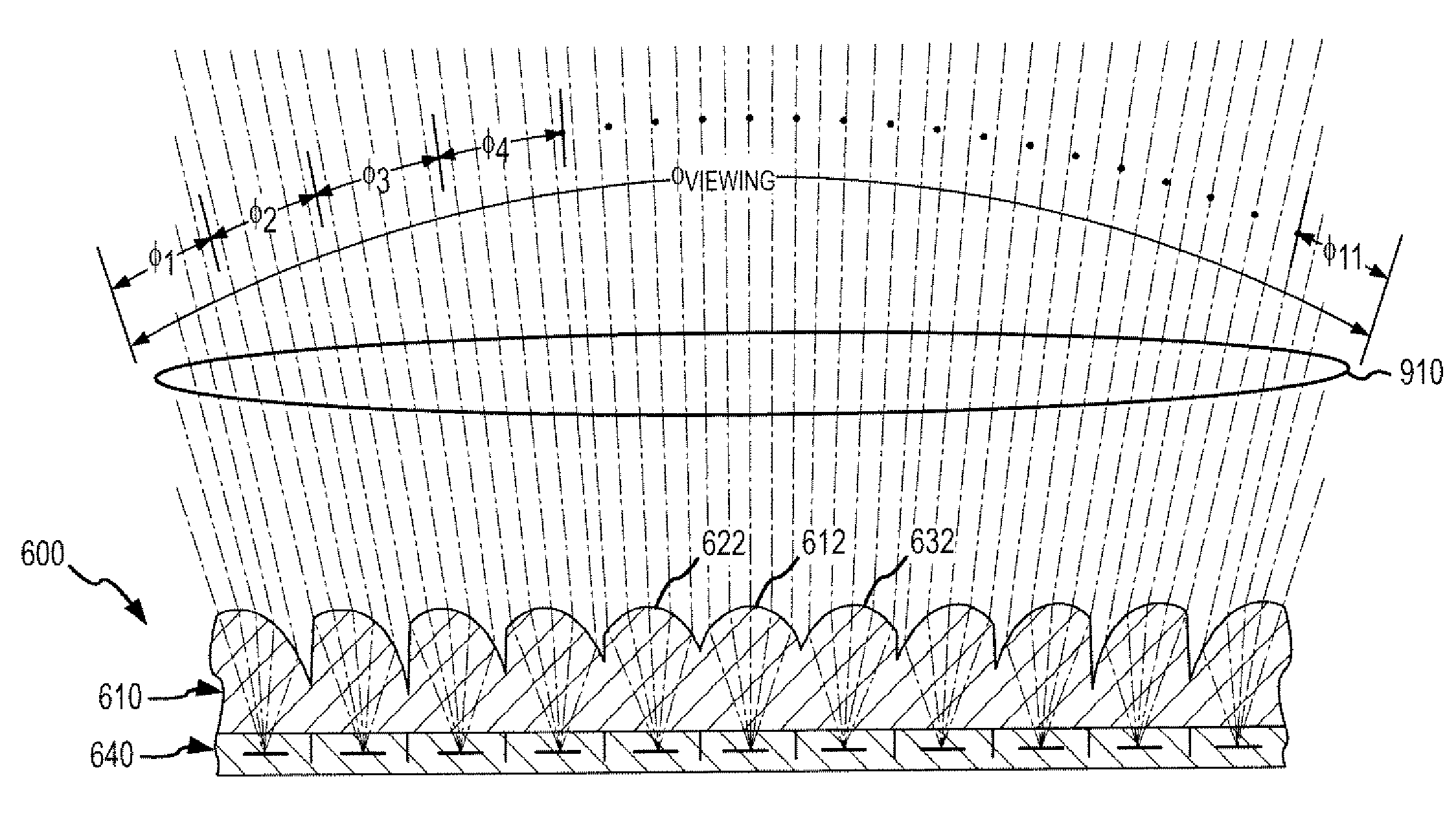
[0027]Briefly, the present invention is directed to lens arrays that can be used to reduce or even replace the use of conventional lenticular material. With conventional lenticular material, numerous elongated or linear lenticules or lenses are provided in a clear or translucent web or layer. Each lenticule is used to provide a viewing angle (e.g., 15 to 40 degrees or the like and more typically about 20 to 35 degrees) through which a plurality of interlaced slices of an image segment are visible to a viewer. For example, an interlaced image may be printed on the smooth side of the lenticular material web with the set of slices, which may number 5 to 20 or more, for a segment of the image being mapped to a particular lenticule such that the slices can be viewed separately as the material or the viewer's line of sight is moved across the viewing angle. The interlaced image with its interlaced image slices or elements can in this way be viewed to achieve visual effects such as 3D, ani...


PUM


Abstract

An assembly for displaying an interlaced image. The assembly includes an interlaced image, which may be digitally or web printed for example, with sets of elongate image elements or slices A lens arrays is provided with a first side proximate the interlaced image such as a planar surface and a second side distal the image with numerous lens sets. Each of the lens sets is paired with one of the sets of the image elements and includes a number of linear or elongate lenses that are each mapped to one to three image elements. The lenses are each configured to focus light from the subset of image elements to a viewer along a focus direction or line. The lenses are configured to provide a lens-specific viewing angle with a focus line, and the focus line to the paired image element subset differs from other lenses or is unique.

Description

CROSS-REFERENCE TO RELATED APPLICATION[0001]This application is related to U.S. application Ser. No. 11 / 558,541, filed Nov. 10, 2006, and entitled Manufacture of Display Devices with Ultrathin Lens Arrays for Viewing Interlaced Images, which is incorporated herein by reference in its entirety.BACKGROUND OF THE INVENTION[0002]1. Field of the Invention[0003]The present invention relates, in general, to lens arrays and devices for use in viewing or displaying images that are interlaced to display animated, three-dimensional (3D), and other images, and, more particularly, to very thin lens arrays, as well as products incorporating such lens arrays and methods of fabricating such lens arrays, that include numerous, repeating sets of lenses or lens microstructures that are specially configured for viewing an interlaced image by pairing each lens in the set or microstructure with only one of (or a smaller subset of) the interlaced image elements or slices.[0004]2. Relevant Background[0005]...

Claims


Application Information

Patent Timeline
Patent Type & Authority Patents(United States)
IPC IPC(8): G02B27/10G03B25/02G02B30/29
CPCG02B3/0025G03B21/602G02B27/2214G02B3/0043G02B30/29G02B30/27
Inventor RAYMOND, MARK A.LANGE, HOWARD G.
Owner GENIE LENS TECH
Why Eureka
Try Eureka