
Low-latency architectures for high-throughput Viterbi decoders

a viterbi decoder and low-latency architecture technology, applied in the field of digital communication, can solve the problems of limited decoding speed of viterbi decoding algorithm, iteration bound, long latency of look-ahead acs precomputation, etc., and achieve the effect of reducing the latency of acs precomputation and high throughput ra

Inactive Publication Date: 2007-12-11
PARHI KESHAB K
View PDF6 Cites 5 Cited by
  • Summary
  • Abstract
  • Description
  • Claims
  • Application Information

AI Technical Summary

Benefits of technology

"The invention describes a method for reducing latency in a Viterbi decoder by combining K-trellis steps and look-ahead branch metrics in a layered manner. This results in a simplified and high-throughput architecture with logarithmic increase in latency compared to traditional look-ahead. The method also ensures that there are no parallel paths between trellis states, which allows for efficient use of look-ahead ACS precomputation. The technical effect of the invention is to decrease latency in the Viterbi decoder and improve its performance."

Problems solved by technology

The decoding speed of the Viterbi decoding algorithm is limited by the iteration bound because the add-compare-select (ACS) recursion in the Viterbi decoding algorithm contains feedback loops.
The main drawback of the traditional M-step look-ahead technique is that it leads to long latency for look-ahead ACS precomputation, especially when very large number of look-ahead steps is required.

Method used


Image

  • Low-latency architectures for high-throughput Viterbi decoders
  • Low-latency architectures for high-throughput Viterbi decoders
  • Low-latency architectures for high-throughput Viterbi decoders

Examples


Embodiment Construction

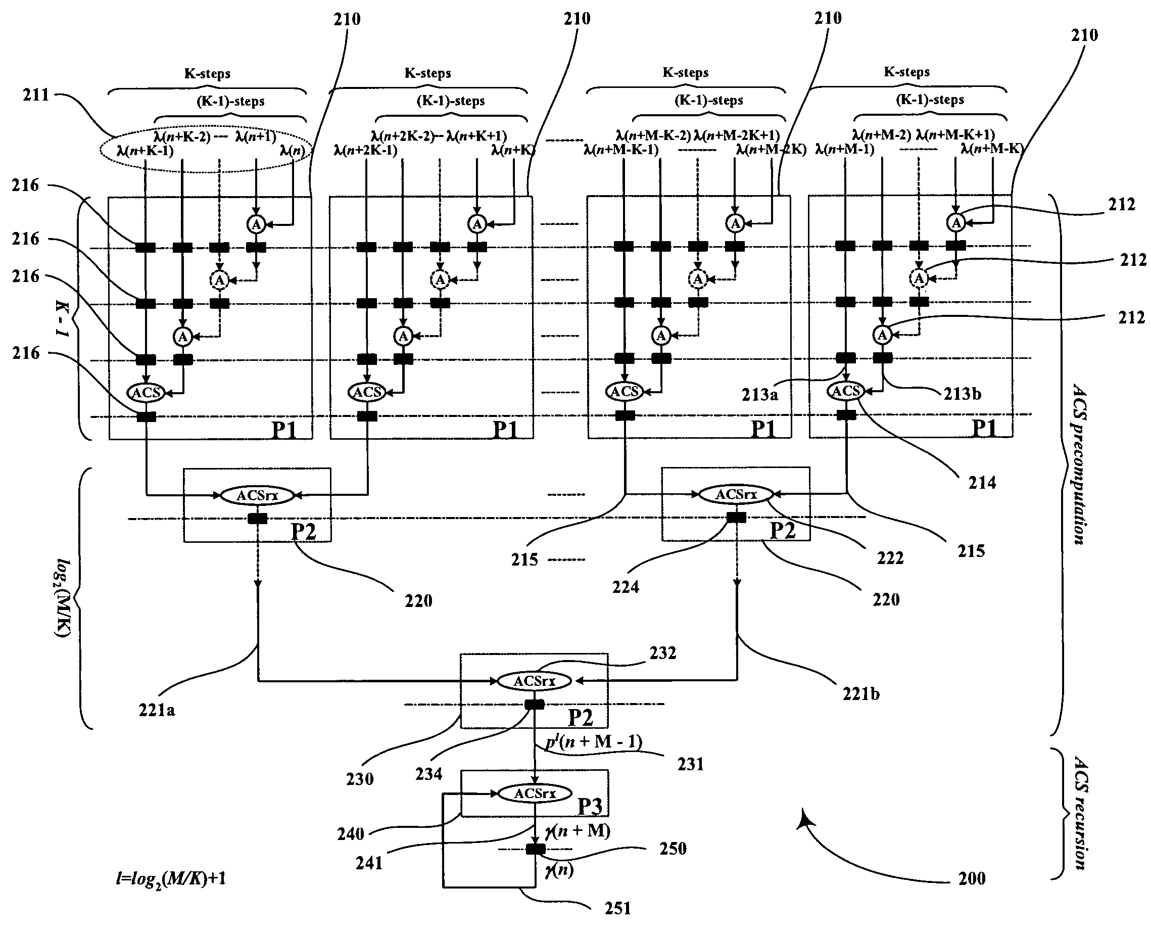
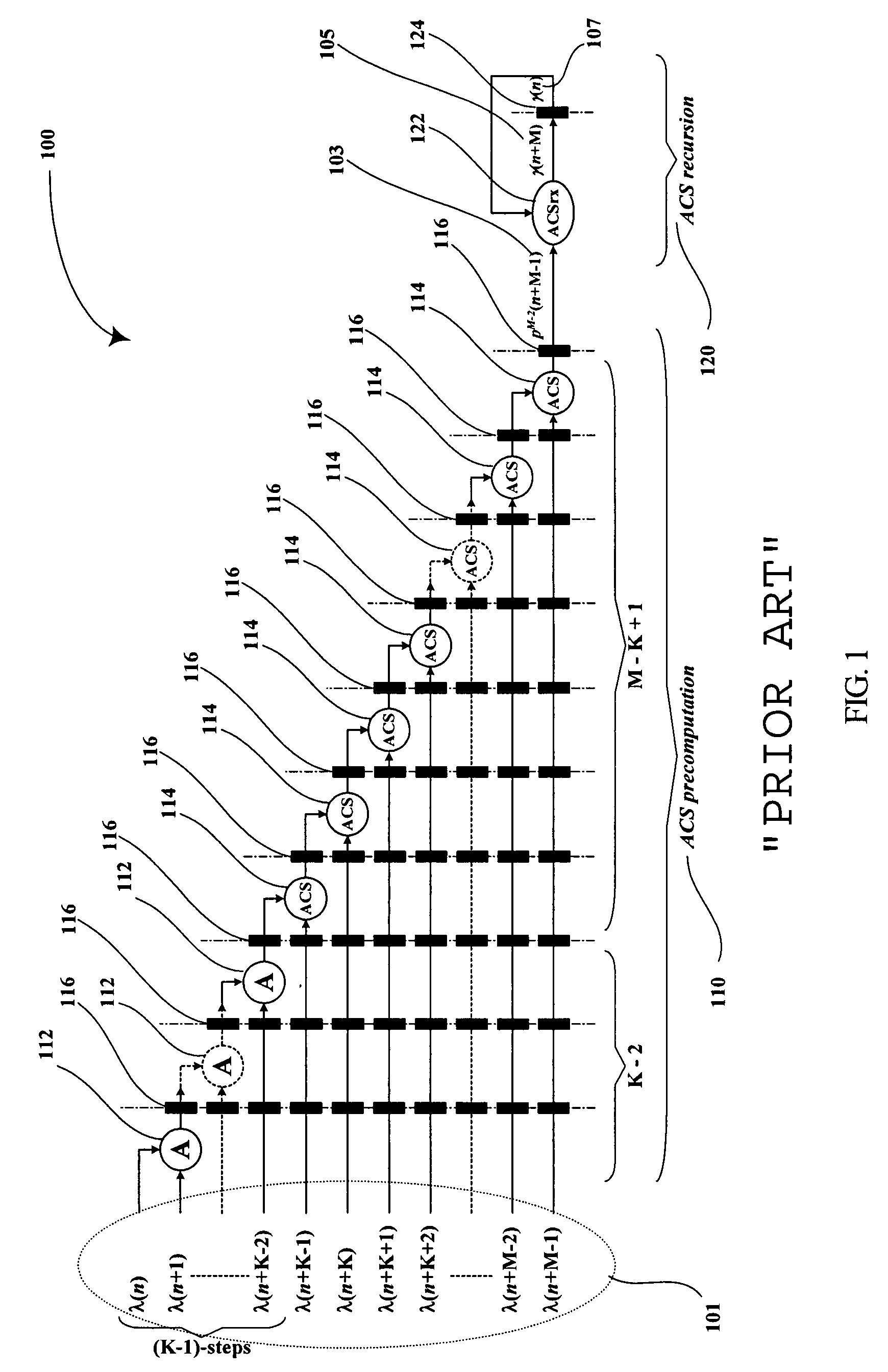
[0024]In the look-ahead technique, the combined branch metrics can be computed outside of the ACS recursion. This allows the ACS loop to be pipelined or computed in parallel. Thereby, the decoding throughput rate can be increased. This is an advantage of the look-ahead technique, which has been explored for Viterbi decoding algorithm and the dynamic programming problems. FIG. 1 illustrates that a circuit 100 consists of ACS precomputation part (circuit 110) and ACS recursion part (circuit 120) for traditional M-step look-ahead Viterbi decoding circuit.

[0025]The ACS precomputation part (circuit 110) consists of 2-input adders (circuit 112), radix-2 ACS circuits (114), and pipelining latches (circuit 116). Each radix-2 ACS circuit consists of two 2-input adders and a radix-2 compare-select (CS) circuit. Circuit 110 uses M-parallel incoming branch metrics (signal 101) for its ACS precomputation. For the first (K-1)-steps branch metrics inputs, compare-select operations are not necessar...


PUM


Abstract

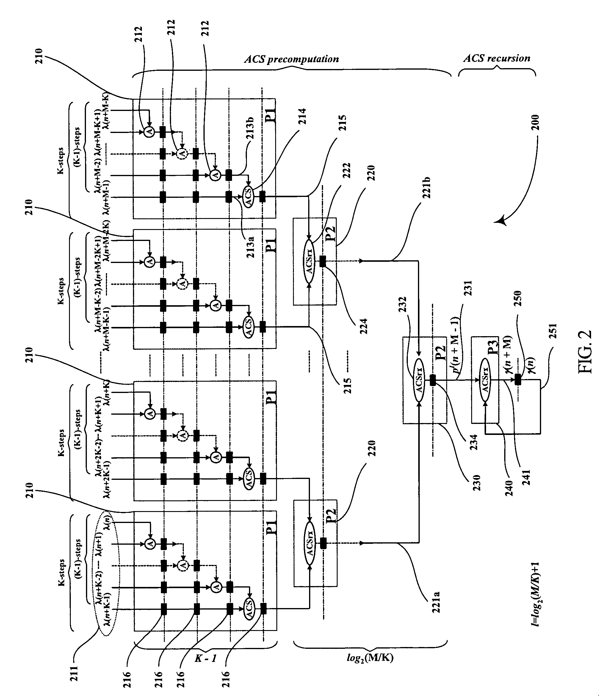
Digital circuits and methods for designing digital circuits are presented. More particularly, the present invention relates to error correction circuits and methods in communications and other systems. In the present invention, a novel K-nested layered look-ahead method and its corresponding architecture, which combine K-trellis steps into one trellis step (where K is the encoder constraint length), are proposed for implementing low-latency high-throughput rate Viterbi decoder circuits. The main idea of the present invention involves combining K-trellis steps as a pipeline structure and then combining the resulting look-ahead branch metrics as a tree structure in a layered manner to decrease the ACS precomputation latency of look-ahead Viterbi decoder circuits. The proposed method guarantees parallel paths between any two trellis states in the look-ahead trellises and distributes the add-compare-select (ACS) computations to all trellis layers. It leads to regular and simple architecture for the Viterbi decoding algorithm. The look-ahead ACS computation latency of the proposed method increases logarithmically with respect to the look-ahead step (M) divided by the encoder constraint length (K) as opposed to linearly as in prior work. The main advantage of this invention is that it has the least latency among all known look-ahead Viterbi decoder circuits for a given level of parallelism.

Description

CROSS REFERENCE TO RELATED APPLICATIONS[0001]This application is a continuation-in-part of U.S. Provisional Patent Application No. 60 / 496,307, filed on Aug. 19, 2003, which is incorporated herein by reference in its entirety.FIELD OF THE INVENTION[0002]The present invention relates to digital communications. More particularly, the present invention relates to error correction circuits and methods in digital communication systems.BACKGROUND OF THE INVENTION[0003]A convolutional code has been widely used in many communication systems as a forward error correction (FEC) method. The Viterbi decoding algorithm is optimum for decoding of the received data, which is transmitted after convolutional encoding.[0004]The decoding speed of the Viterbi decoding algorithm is limited by the iteration bound because the add-compare-select (ACS) recursion in the Viterbi decoding algorithm contains feedback loops. A look-ahead technique, which combines several trellis steps into one trellis step in tim...

Claims


Application Information

Patent Timeline
Patent Type & Authority Patents(United States)
IPC IPC(8): H03M13/03H03M13/41
CPCH03M13/395H03M13/4107H03M13/3961
Inventor PARHI, KESHAB K.KONG, JUNJIN
Owner PARHI KESHAB K
Learn More