Diversity reception device and diversity reception method

a technology of diversity and reception device, applied in the field of diversity receiver, can solve the problems of difficult to improve the reception performance of diversity, the reception cannot be improved over the maximum ratio combining diversity, and the receiver cannot obtain better receiving performance, etc., to achieve the effect of large diversity effect, improved receiving performance, and large diversity

Inactive Publication Date: 2007-12-18
MITSUBISHI ELECTRIC CORP
View PDF24 Cites 42 Cited by
  • Summary
  • Abstract
  • Description
  • Claims
  • Application Information

AI Technical Summary

Benefits of technology

[0012]The diversity receiving method of the present invention adaptively switches between selection diversity and equal gain combining diversity for each subcarrier component according to power values of the received signals on the demodulation paths, so in comparison with conventional diversity receiving methods using only selection diversity or only equal gain combining diversity, it can provide a larger diversity effect and improved receiving performance, and a diversity receiver producing a large diversity effect can be implemented with less circuitry than when maximal ratio combining diversity is practiced.

Problems solved by technology

At each point in time, accordingly, they cannot obtain better receiving performance than the individual received power obtained from one of the received signals in the two demodulation paths.
Among conventional diversity receivers, selection diversity receivers, for example, can operate with small circuitry because they simply use one of the received signals on the pair of demodulation paths, but there has been a problem in that it is difficult to improve their receiving performance.
Although equal gain combining diversity receivers require only simple equalizers to be added and can accordingly operate with comparatively small circuitry, and although they can provide better reception than with selection diversity, there has been a problem in that their reception cannot be improved over that of maximal ratio combining diversity.
There has also been a problem in that as the difference between the received signals on the pair of demodulation paths increases, the receiving performance of equal gain combining diversity receivers is degraded.
Maximal ratio combining diversity receivers can provide better receiving performance than selection or equal gain combining diversity receivers, but there has been a problem in that they require circuitry for generating weighting coefficients according to the (estimated) received signal power ratio and further multiplying the received signal powers by the weighting coefficients, resulting in larger circuit scale.

Method used


Image

  • Diversity reception device and diversity reception method
  • Diversity reception device and diversity reception method
  • Diversity reception device and diversity reception method

Examples


first embodiment

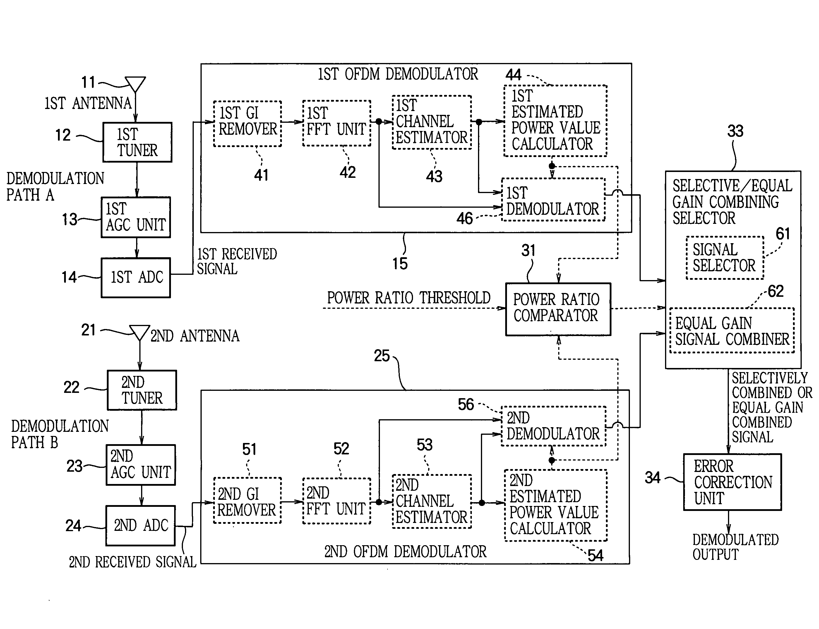
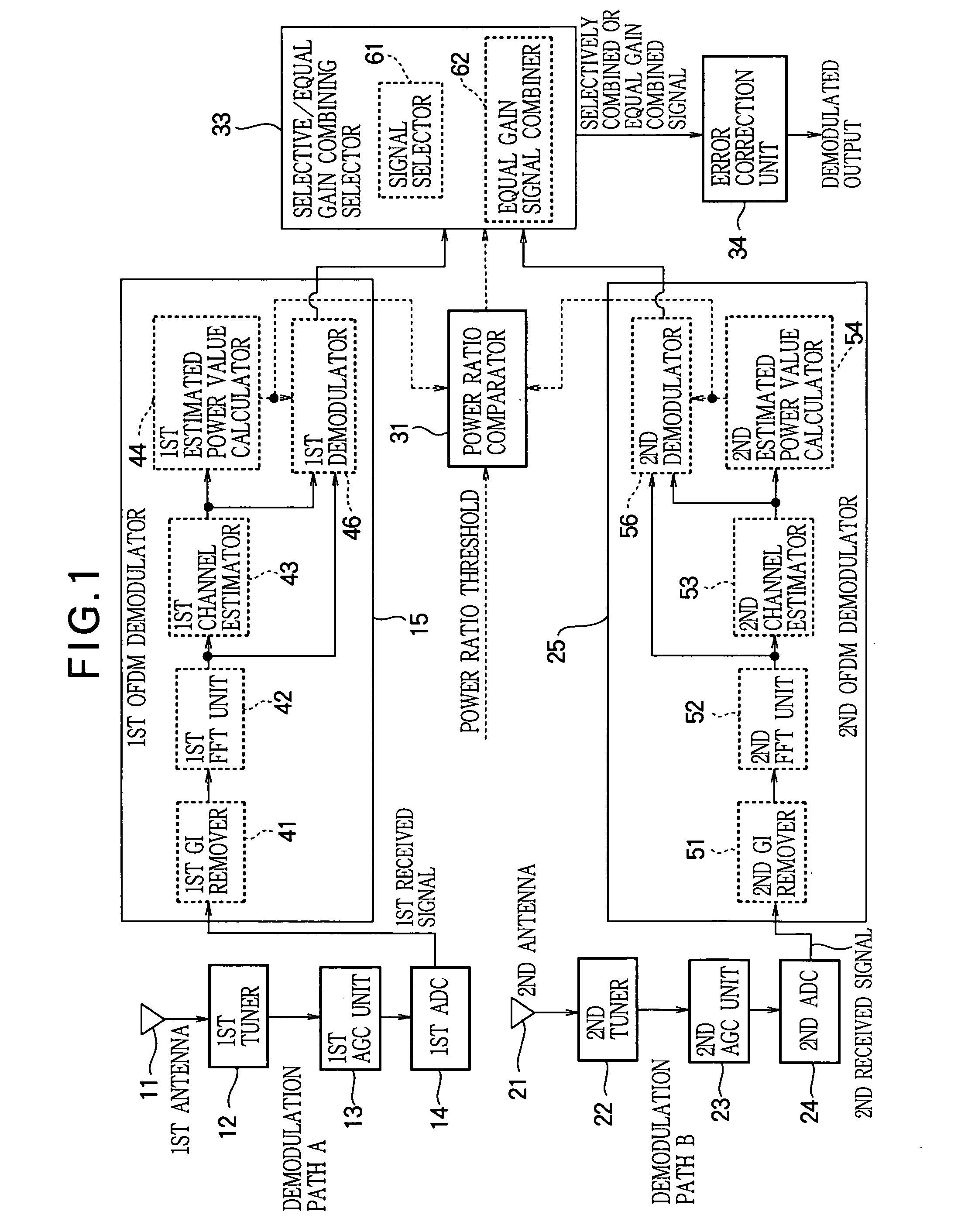
[0036]FIG. 1 is a block diagram illustrating the diversity receiver in the first embodiment.

[0037]As OFDM signal demodulation paths, the diversity receiver has two demodulation paths: demodulation path A and demodulation path B. Demodulation path A has a first antenna 11, a first tuner 12, a first AGC (Automatic Gain Control) unit 13, a first ADC (analog-to-digital converter) 14, and a first OFDM demodulator 15. Demodulation path B has a second antenna 21, a second tuner 22, a second AGC unit 23, a second ADC 24, and a second OFDM demodulator 25.

[0038]In the diversity receiver illustrated in FIG. 1, the first antenna 11 and second antenna 21 receive wireless signals that have been modulated for transmission. The first tuner 12 and second tuner 22 convert the frequency of the received wireless signals to a predetermined frequency band.

[0039]The first AGC unit 13 and second AGC unit 23 adjust the gain levels of the frequency-converted analog signals. The gain level adjustment performe...

second embodiment

[0080]The first embodiment provides a structure in which adaptive combining diversity is carried out using power estimates Pes—A, Pes—B output from the estimated power value calculators 44, 54. In the second embodiment, the power of the subcarrier components is calculated from the signal output after the Fourier transform, and adaptive combining diversity is carried out using the calculated result. In the description below, subcarrier component power is also referred to as subcarrier power, and the value of the subcarrier power is also referred to as a subcarrier power value.

[0081]FIG. 5 is a block diagram showing a diversity receiver in the second embodiment.

[0082]The structure of the diversity receiver in FIG. 5 is the same as shown in FIG. 1 in the first embodiment, except for the first OFDM demodulator 15a, second OFDM demodulator 25a, power ratio comparator 31a, first subcarrier power calculator 45, and second subcarrier power calculator 55, and except that there are no output ...

third embodiment

[0092]The diversity receivers in the first and second embodiments are structured so that estimated power or subcarrier power is determined from frequency domain signals output from the FFT units 42 and 52, based on which adaptive combining diversity is carried out. In the third embodiment, the power levels of the signals input through the antennas 11, 21 are determined and adaptive combining diversity is carried out by using these power levels, as described below.

[0093]FIG. 6 is a block diagram showing the diversity receiver in the third embodiment.

[0094]The structure of the diversity receiver in FIG. 6 is the same as shown in FIG. 1 in the first embodiment or in FIG. 6 in the second embodiment, except for the first OFDM demodulator 15b, second OFDM demodulator 25b, power ratio comparator 31b, input connections to the AGC units 13, 23, and output connections from the ADC's 14, 24.

[0095]The operation of the diversity receiver in the third embodiment will be described below. Descripti...


PUM


Abstract

The circuit size of a diversity receiver for an orthogonal frequency division multiplexing signal is reduced, and the diversity effect is increased, by providing a power ratio comparator that calculates a difference value as a ratio of powers derived from channel estimation results for subcarrier components received from two antennas (11), (21) and compares the calculated difference value with a predetermined threshold, and a selective / equal gain combining selector (33) that outputs one of the received demodulated signals when the comparison result indicates that the calculated difference value is greater than the threshold value.

Description

FIELD OF THE INVENTION[0001]The present invention relates to a diversity receiver having a plurality of demodulation paths, and to its receiving method.BACKGROUND ART[0002]The diversity receivers found in the prior art first compare estimated received power values of the carrier waves of the received signals on each of two demodulation paths at each point in time, and select and output the received signal with the larger estimated value; this is generally known as selection diversity (also referred to below as the selection system or selective diversity). That is, of the two received signals at each point in time, they selectively output the received signal with the better reception conditions, and do not use the received signal with the inferior reception conditions. At each point in time, accordingly, they cannot obtain better receiving performance than the individual received power obtained from one of the received signals in the two demodulation paths.[0003]To improve the receiv...

Claims


Application Information

Patent Timeline
Patent Type & Authority Patents(United States)
IPC IPC(8): H04B7/08H04L1/20H04J11/00H04L27/26
CPCH04B7/0808H04L1/20H04B7/084H04L27/2647
Inventor IDO, JUN
Owner MITSUBISHI ELECTRIC CORP
Why Eureka
Try Eureka