

High efficiency plasma display panel (PDP) provided with electrodes within laminated dielectric barrier ribs
a dielectric barrier and plasma display technology, applied in the direction of gas-filled discharge tubes, discharge tubes/lamp details, incadescent body mounting/support, etc., can solve the problems of voltage drop in the sustaining electrode pairs, reduce the transmission of visible light from the fluorescent layers, reduce the brightness of the pdp, etc., to improve the transmission of visible light, increase the light emission efficiency, and increase the brightness
- Summary
- Abstract
- Description
- Claims
- Application Information
AI Technical Summary
Benefits of technology
Problems solved by technology
Method used
Image

Examples
Embodiment Construction
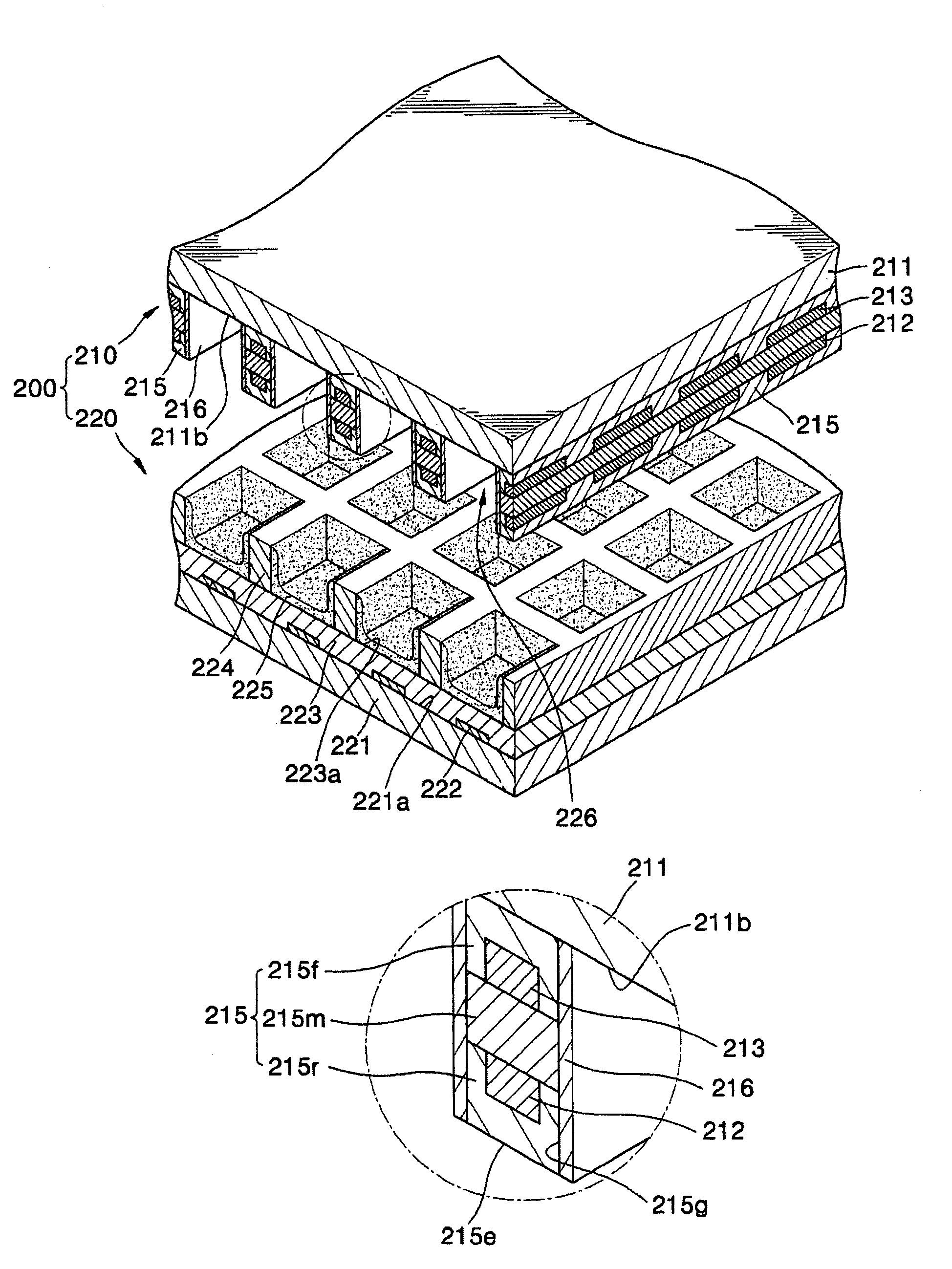
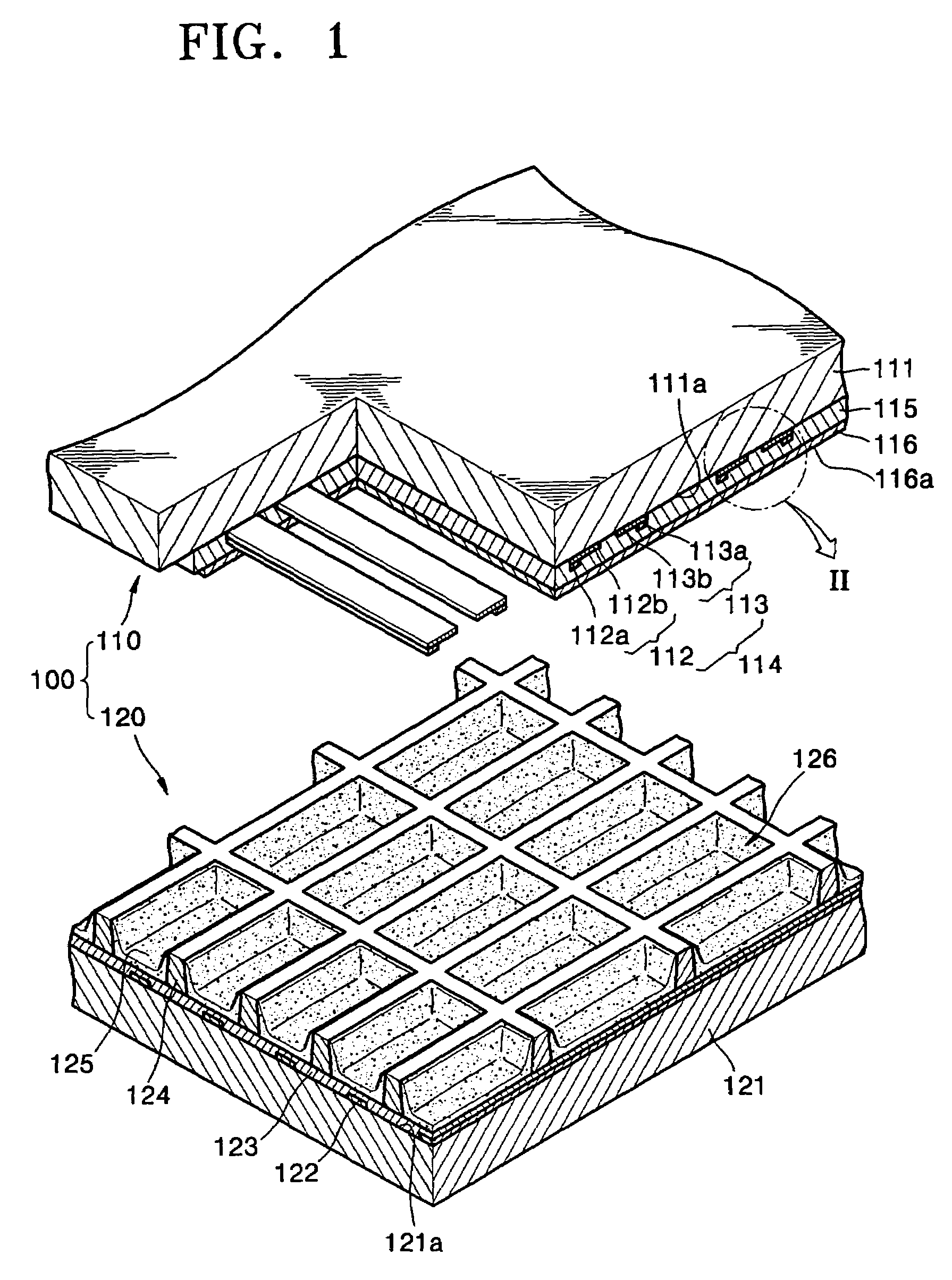
[0031]FIG. 1 is a cutaway exploded perspective view of a PDP. Referring to FIG. 1, the structure of a front panel 110 and a rear panel 120 of an alternate type three electrode surface discharge PDP 100 is shown.
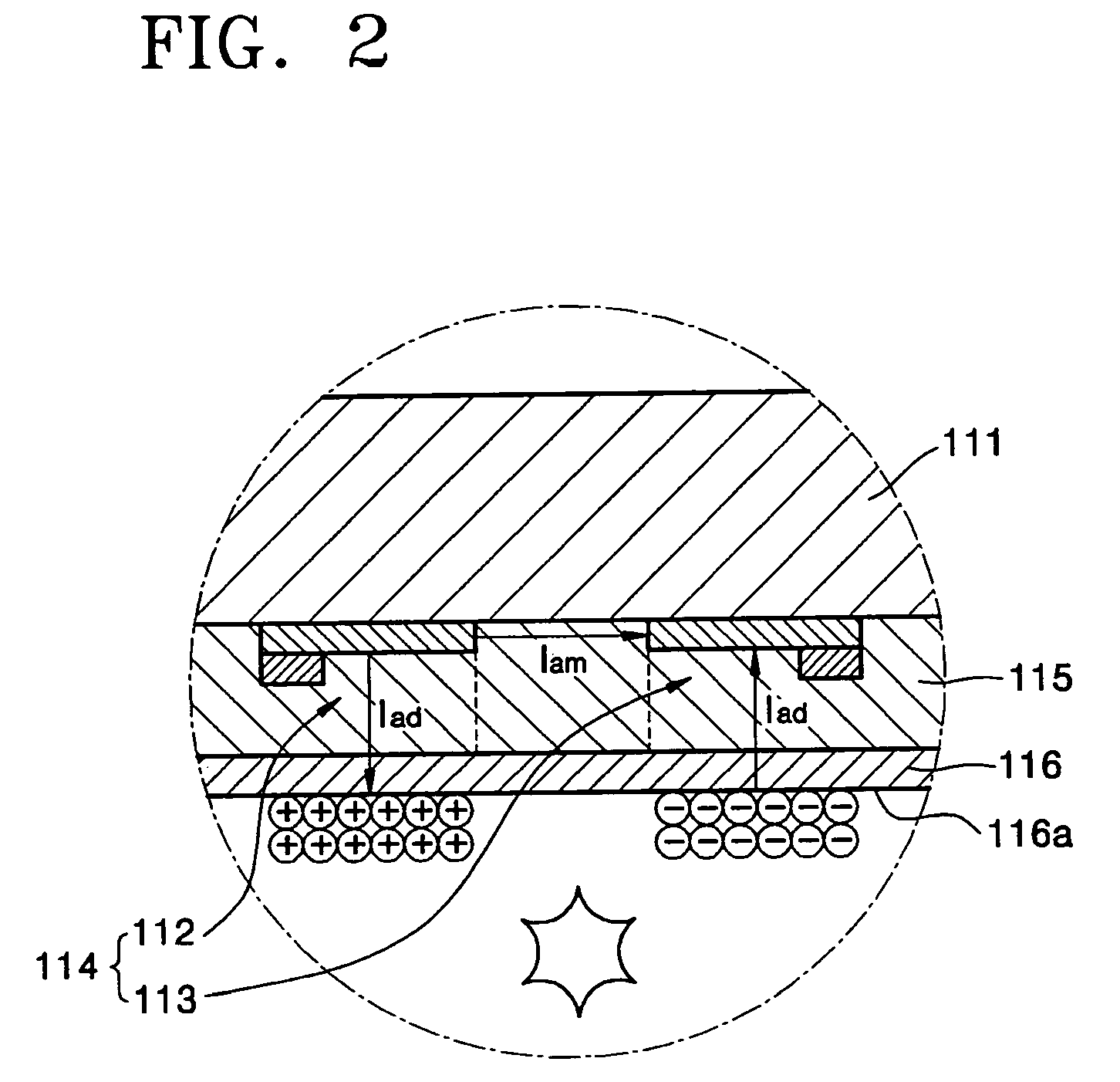
[0032]The front panel 110 comprises a front substrate 111, sustaining electrode pairs 114 including Y electrodes 112 and X electrodes 113 formed on the rear surface 111a of the front substrate 111, a front dielectric layer 115 covering the sustaining electrode pairs 114, and a protection film 116 covering the front dielectric layer 115. Each of the Y electrodes 112 and X electrodes 113 includes transparent electrodes 112b and 113b and bus electrodes 112a and 113a. The bus electrodes 112a and 113a are connected to connecting cables (not shown) on the left and right sides of the PDP 100.
[0033]The rear panel 120 comprises a rear substrate 121, address electrodes 122 crossing the sustaining electrode pairs 114 on the front surface 121a of the rear substrate 121, a rear dielectric...
PUM
 Abstract
Description
Claims
Application Information