
Seamless steel tubes and method for producing the same

a technology of seamless steel tubes and steel tubes, which is applied in the direction of manufacturing tools, furnaces, heat treatment equipment, etc., can solve the problems of cracking along the weld line, method cannot be applied, and small diameter at both ends, etc., and achieve excellent cold workability, excellent torque (nm), and excellent torsion fatigue strength.

Active Publication Date: 2008-01-08
NIPPON STEEL CORP
View PDF23 Cites 6 Cited by
  • Summary
  • Abstract
  • Description
  • Claims
  • Application Information

AI Technical Summary

Benefits of technology

[0017]As afore-mentioned, in the case that seamless steel tubes are used as hollow shift blanks for hollow drive shafts, it is required not only to prevent any cracking attributable to a reducing and / or spinning process of tube ends, but also to harden through the whole thickness from the outside surface to the inside surface by the heat treatment after cold working and to secure high toughness as well. And further, in order to achieve longer service life as the hollow drive shaft, it becomes necessary to secure cold workability, hardenability, toughness and torsion fatigue strength concurrently
[0018]Incidentally, in the seamless steel tubes proposed by the prior art, there has been almost no study from the metallurgical aspect to specify the chemical compositions in order for the hollow shaft blanks to exhibit excellent cold workability, hardenability, toughness and torsion fatigue characteristic.
[0019]In other words, although it is not difficult for any of these features required for hollow drive shafts to be improved individually, it has been perceived based on the knowledge to date that all of them cannot be improved concurrently. For instance, as it is effective to increase the strength of the steel in order to secure high fatigue strength, the steel tubes to be used as starting materials can be made to have high strength, which instead attributes to reduce the cold workability.

Problems solved by technology

However, this method cannot be applied for the case that the hollow portion has a large diameter but the diameter at both ends is small.
Accordingly, when welded tubes are used as steel tube blanks to make hollow drive shafts, there is an issue that any cracking should occur along the weld line during forming operation and / or any fatigue crack develops along the weld line in the fatigue test to be conducted after forming operation.
Thus, at present there is insufficient reliability in using welded tubes as hollow shaft blanks for making hollow drive shafts.
However, in hollow drive shafts which have been proposed thus far, the metallurgical aspect of seamless steel tubes has been hardly focused and studied.
Nonetheless, it is not possible to obtain seamless steel tubes having excellent cold workability as well as excellent fatigue characteristics by simply stipulating Carbon Equivalent (Ceq) for the steel tube for the drive shaft and for the balance weight.
By reason of this, it is difficult for the automobile propeller shaft disclosed in the Japanese Patent Application Publication No. 06-341422 to be applied as an one-piece type hollow drive shaft.
In the disclosed method, detail chemical compositions are stipulated while Ti is not contained and N is not specified at all, whereby even if B may be added, the steel composition is not configured to sufficiently impart harden ability.
Further, the steel compositional design is not made in consideration of cold workability and fatigue characteristics, so that the manufacturing method disclosed in the Japanese Patent Application Publication No. 07-018330 is unlikely applied to produce seamless steel tubes as starting materials suitable for one-piece type hollow drive shafts.
However, the material grade disclosed in EXAMPLES is carbon steel corresponding to S48C specified in JIS Standard, and it seems that there is no intention to stipulate specific chemical compositions for purpose of improving cold workability, hardenability and fatigue characteristics.
In the manufacturing method disclosed by the Japanese Patent Application Publication No. 08-073938, detail chemical compositions of steel stocks to be used are stipulated, but similarly to the manufacturing method described in the Japanese Patent Application Publication No. 07-018330, even if B and / or Ti may be added, the steel composition is not configured too sufficiently impart hardenability and further, the steel compositional design is not made in consideration of cold workability and fatigue characteristics, so that it is unlikely applied to produce tube blanks suitable for one-piece type hollow drive shafts.
In addition, since Cr is not contained in the chemical compositions, hardenability as well as fatigue strengths are not sufficient, whereby this is not; pertinent to steel tubes suitable for one-piece type hollow drive shafts.
However, in this high carbon steel tubes by the Japanese Patent Application Publication No. 2001-355047, warm working is required to obtain the targeted microstructure to thereby increase production costs, and what is more, the disclosed chemical compositions are not pertinent to one-piece type hollow drive shafts which should concurrently satisfy cold workability, hardenability and fatigue characteristic.

Method used


Image

  • Seamless steel tubes and method for producing the same
  • Seamless steel tubes and method for producing the same
  • Seamless steel tubes and method for producing the same

Examples


example 1

[0101]A vacuum melting process is applied to prepare various steel grades designated by Steel Nos. 1 through 32 (Steel Nos. 1 through 21: Inventive, Steel Nos. 22 through 32: Comparative) with chemical compositions shown in Tables 1 and 2, which are rolled into steel blanks (billets) to be subjected to the tube making process obtaining steel tubes of 50.8 mm in outside diameter and 7.9 mm in wall thickness.

[0102]

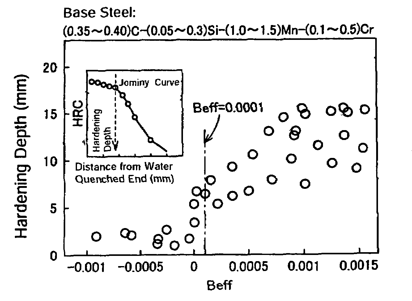
TABLE 1Table 1Chemical Composition (mass %, Balance: Fe and Impurities)ConditionalSteelCu,Ca,EquationNoCSiMnPSCrAlTiNBOMo, NiV, Nb, ZrMg, REMNeffBeff10.330.071.620.0170.00190.490.0220.0190.00110.00080.0020−0.00340.000820.360.071.660.0040.00020.520.0190.0160.00510.00100.00100.00030.000730.370.061.710.0110.00080.490.0220.0150.00450.00070.00080.00010.000640.380.041.360.0020.00120.310.0200.0170.00340.00070.0008−0.00120.000750.330.071.320.0040.00090.590.0130.0230.00570.00070.0020−0.00080.000760.360.311.650.0020.00400.410.0230.0250.00210.00090.0015−0.00400.000970.340.031.690.0060....

example 2

[0112]Among the Inventive Examples shown foregoing Table 3, applying too much cold work rate may cause cracking, although no cracking should occur during the typical cold working or during the typical spinning process thanks to the imparted fundamental features. For instance, said Steel No. 1 shown in foregoing Table 3 does not; exhibit; any cracking when the cold work rate expressed by the cross-sectional area reduction rate is 60%, but likely exhibit cracking at 80% in the cold work rate.

[0113]In the case that too much reduction rate of cross-sectional area is applied in cold working, how normalizing or annealing at the intermediate stage of cold working acts or, in the alternative, spheroidizing annealing before or after the cold working acts is shown in Table 4. The absence or presence of cracking in Table 4 is indicated as follows: a symbol ∘ denotes no cracking: a symbol x denotes the occurrence of cracking. And then, an evaluation by applying spinning to make a spline is cond...


PUM

PropertyMeasurementUnit
mass %aaaaaaaaaa
grain sizeaaaaaaaaaa
diameteraaaaaaaaaa

Abstract

A seamless steel tube comprising, in mass %, C: 0.30 to 0.50%, Si: 0.5% or less, Mn: 0.3 to 2.0%, P: 0.025% or less, S: 0.005% or less, Cr: 0.15 to 1.0%, Al: 0.001 to 0.05%, Ti: 0.005 to 0.05%, N: 0.02% or less, B: 0.0005 to 0.01% and O (oxygen): 0.0050% or less, wherein Beff defined in following equation (a) or (b) takes a value of 0.0001 or more, where Beff=B−10.8×(N−14×Ti / 47.9) / 14—(a) when Neff=N−14×Ti / 47.9≧0, and Beff=B—(b) when Neff=N−14×Ti / 47.9<0, thus enabling to provide seamless steel tubes having excellent cold workability, hardenability, toughness and torsion fatigue strength and being most suitable for hollow shaft blanks for use in making one-piece type hollow drive shafts as well.

Description

BACKGROUND OF THE INVENTION [0001]The present invention relates to seamless steel tubes to be used as hollow shaft blanks which are better fitted to reduce the weight of drive shafts used in automobiles, and more particularly to seamless steel tubes having excellent, cold workability, hardenability, toughness and torsion fatigue strengths as well as being most suitable as starting materials for making hollow drive shafts by applying heat treatment subsequent to cold swaging of both ends thereof, and a method for producing the same.[0002]From the view point of global environment protection, it is highly demanded to reduce the weight of car-body to improve the fuel efficiency. In this regard, there have been various trials that solid members among automobile parts are replaced with hollow members. In these trials, a drive shaft which transmits the driving force to the wheel is also attempted to be made from a hollow blank.[0003]The purpose of making automobile parts to have a hollow s...

Claims


Application Information

Patent Timeline
Patent Type & Authority Patents(United States)
IPC IPC(8): B21B19/04B21B3/00C21D1/32C21D8/10C21D9/08C22C38/00C22C38/38C22C38/58
CPCC21D8/105C21D9/08C22C38/38Y10S72/70C22C38/002C22C38/005C22C38/02C22C38/06C22C38/28C22C38/30C22C38/32
Inventor KONDO, KUNIOARAI, YUJI
Owner NIPPON STEEL CORP
Learn More