Low voltage electronic motor wire termination

a low-voltage electronic and motor technology, applied in the direction of electric cable installation, dynamo-electric components, supports/encloses/casings, etc., can solve the problems of dc motor elements that require additional maintenance, brush and commutator wear that requires disassembly of the machine, and people working around the motor are exposed to a significant risk of electric shock, so as to achieve simple and robust

Inactive Publication Date: 2008-01-08
KOLLMORGEN CORP
View PDF4 Cites 15 Cited by
  • Summary
  • Abstract
  • Description
  • Claims
  • Application Information

AI Technical Summary

Benefits of technology

[0009]Accordingly, the present invention provides a simple and robust design that resolves both the operational design and safety issues discussed above. An embodiment of the invention is directed to an insulating plug and a conductor to carry current between an exterior connection point and an internal connection point.
[0011]It is an object of the invention to provide an easily accessible apparatus to conduct drive current from an external AC power supply to the individual AC phase coils that constitute the AC motor's stator. During motor assembly, the insulating plug is inserted through an insertion aperture in the motor housing. The invention thereby, implements a close-profile robust exterior connection point. Accordingly, the invention provides an easily accessible solution to the problems discussed above. The accessibility of the connections significantly reduces the steps necessary to produce a robust operational motor.
[0012]It is another object of the invention to reduce the complexity of an AC motor manufacturing process and provide design flexibility. Specifically, the invention facilitates a significant degree of flexibility with regard to the placement of the external terminals around the motor housing. Depending on the specified operational requirements, the insulating plug aperture may be defined within the motor housing anywhere that is convenient for the AC motor design. For example, if a specific operating environment had been previously designed for a DC motor terminal configuration, the present invention allows the AC motor exterior terminal connections to replicate the DC configuration. Previously, it was necessary to re-design the operating environment to suit the AC motor's centrally located external terminal connections. Moreover, the housing apertures may be changed during manufacturing the motor housing to any location by adjusting the stamp template used to form the aperture in the housing.

Problems solved by technology

DC motor elements often require additional maintenance because of this connection of moving mechanical parts.
For instance, brush and commutator wear require disassembly of the machine and replacement of these parts.
People working around the motor are therefore exposed to a significant risk of electric shock.
Moreover, in day-to-day operation this type of motor design is often mishandled by users that attempt to lift the motor by wires 205.
This type of misuse increases the risk of live electric wires becoming unfastened from their terminals 210 and further increases the risk of electric shock.
The existence of the layer of insulation means that the bundle of wires cannot be readily terminated to the terminal conductor.
This is due to the high temperatures required to vaporize off the layer of insulation which eliminates brazing and the contaminating effect of the vaporized insulation layer to the resulting bundle strength which makes electrical resistance fusing or welding a problem.
Removal of the insulation layer on each individual wire is possible but time consuming.

Method used


Image

  • Low voltage electronic motor wire termination
  • Low voltage electronic motor wire termination
  • Low voltage electronic motor wire termination

Examples


Embodiment Construction

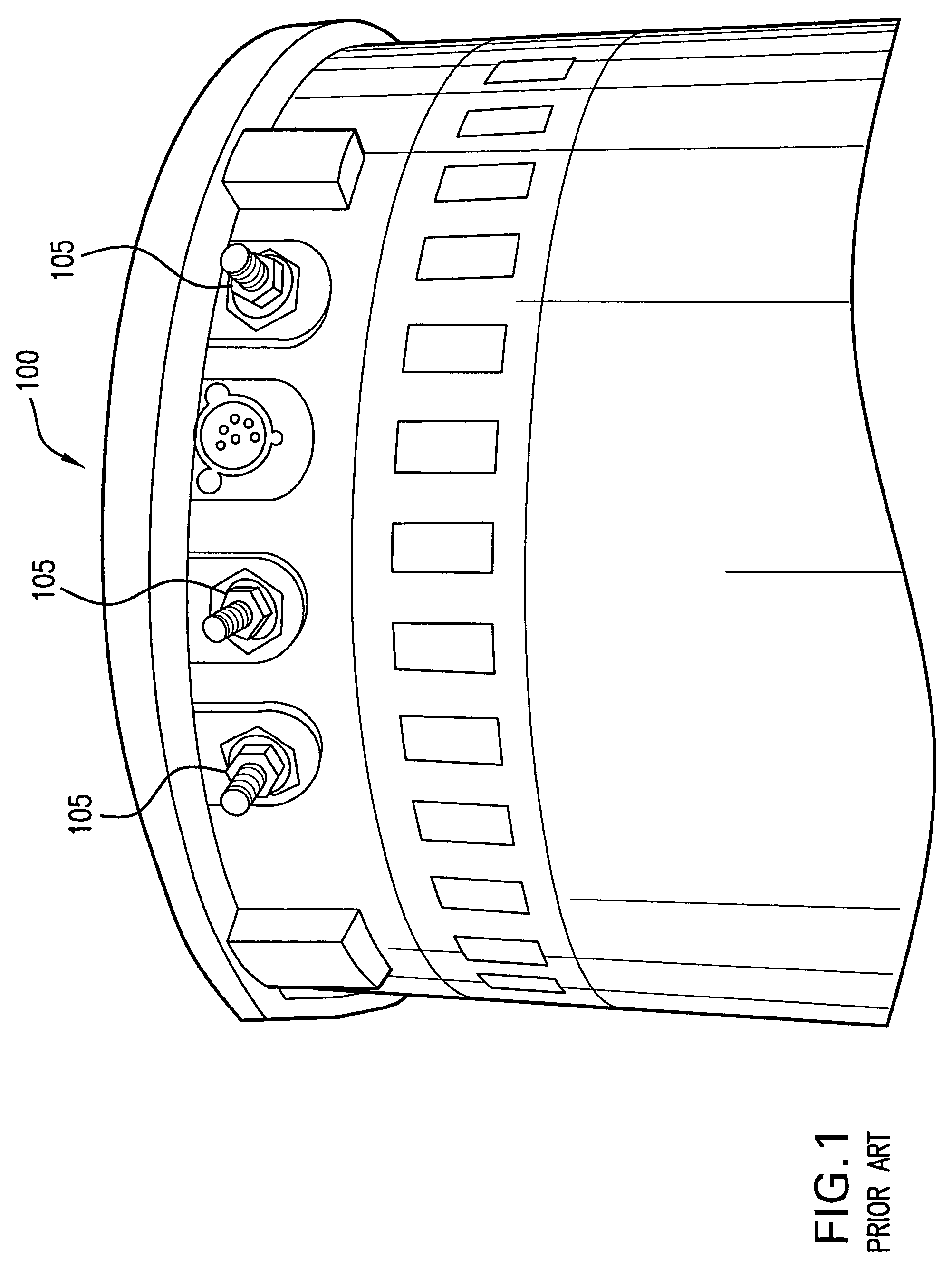
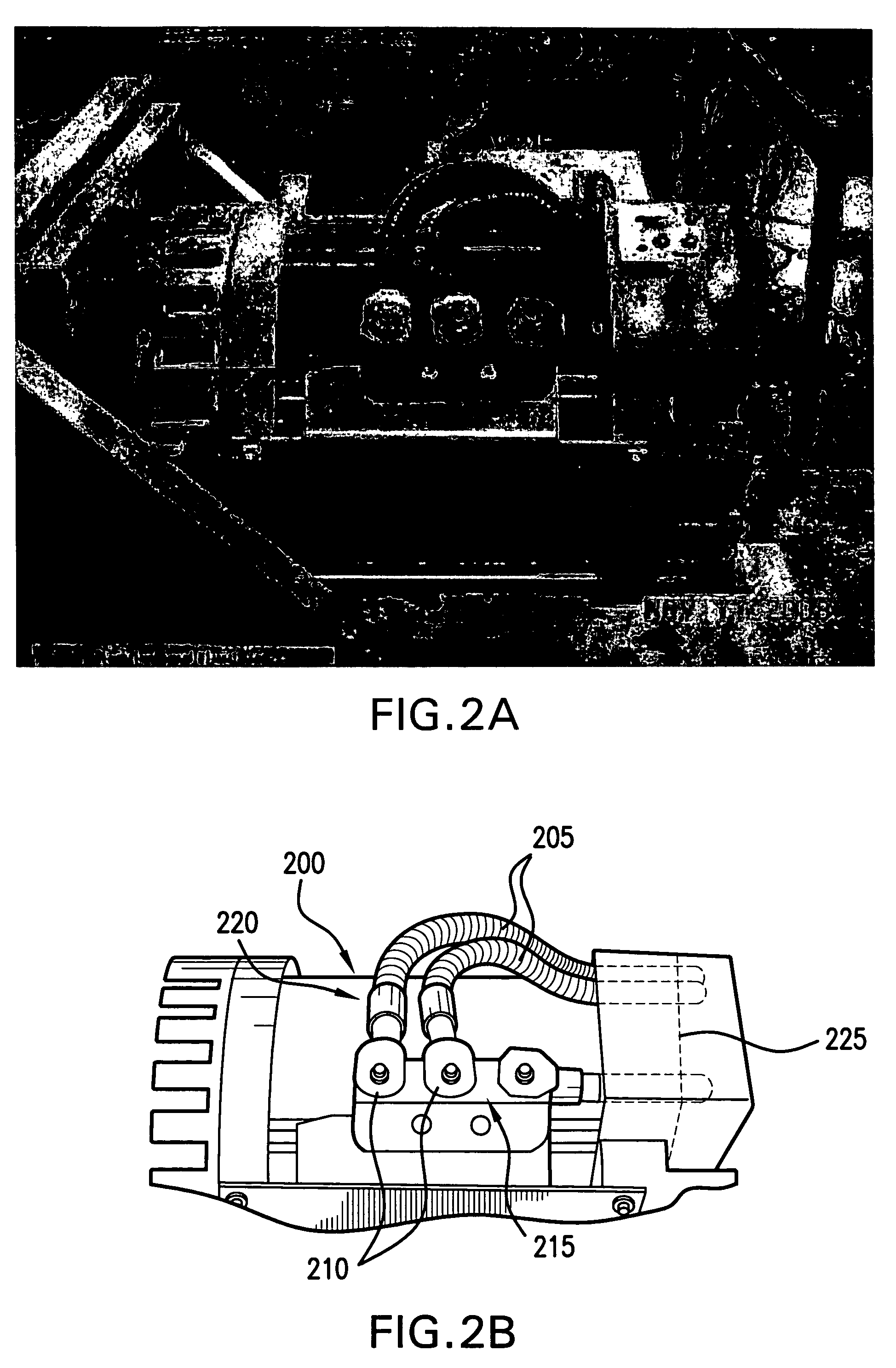
[0026]The invention provides a greater degree of flexibility for AC motor connection terminal designs, as well as addressing a variety of safety concerns related to conventional AC motor connection terminal designs. Previously, AC motor drive current was supplied to a conventional AC motor through power cables connected to an exterior AC connection terminal block (illustrated in FIGS. 2A and 2B). The connection terminal block facilitated an external connection with lead wires that run externally from the connection terminal block to an end of the AC motor. The lead wires entered the AC motor through an aperture in the center of an end bell of the motor and were connected directly to the respective AC phase coils.

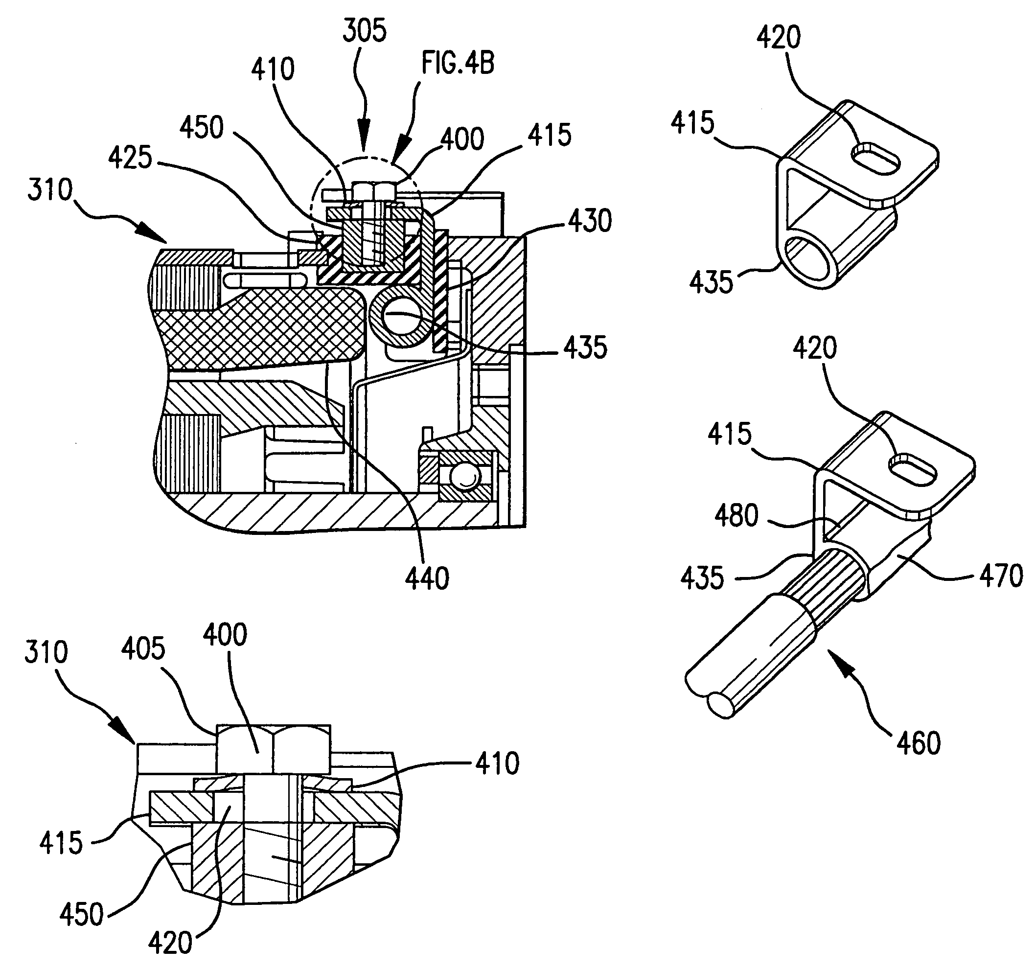
[0027]In contrast to the conventional AC motor, the invention as illustrated in FIGS. 3A and 3B, provides a simple, low profile, robust means of terminating AC phase coil windings. The lead wire connections are made internal to the motor housing.

[0028]FIG. 3A is a black and ...


PUM


Abstract

The present invention provides a simple and robust design implementing an easily accessible external terminal connection point for supplying drive current to an AC motor. An embodiment of the invention is directed to an insertion plug and a conductor formed within the insertion plug. Specifically, the conductor acts as a current bus through an insertion aperture defined in a motor housing. The interior end of the conductor acts as an interior connection terminal for an AC phase coil, whereas the exterior end of the conductor is configured to accept an external motor drive source power cable. Advantageously, the modularity of the insertion plug design and a modified insertion housing aperture stamping program provide significant flexibility with regard to placement of the connection terminal. This aspect of the invention allows the connection terminals, as well as a corresponding motor housing to be customized for pre-existing mechanical designs and assemblies.

Description

RELATED APPLICATION[0001]The instant application hereby claims priority to the U.S. provisional patent application Ser. No. 60 / 519,968 titled, “Low Voltage Electronic Motor Wire Termination” filed on Nov. 13, 2003, which is incorporated by reference herein.FIELD OF THE INVENTION[0002]This invention relates generally to alternating current (AC) motors and, more particularly, to connection terminals used to provide drive current to a motor.BACKGROUND OF THE INVENTION[0003]In the past, electric forklifts, wheel chairs and golf carts have traditionally been powered by direct current (DC) motors. Typically, DC motors are longer than a similarly powered AC motor, because they require additional operational elements such as a brush commutator. The commutator provides a connection point between the current driving the motor and the moving parts of the motor. DC motor elements often require additional maintenance because of this connection of moving mechanical parts. For instance, brush and ...

Claims


Application Information

Patent Timeline
Patent Type & Authority Patents(United States)
IPC IPC(8): H02K5/22H01R4/28H01R11/12H02GH02K11/00
CPCH01R11/12H02K5/225
Inventor BOYLAND, JOHNMCGUIRE, DANHARRIS, CRAIGKLUEVER, RONALD
Owner KOLLMORGEN CORP
Why Eureka
Try Eureka