Low-power driven display device

a display device and low-power technology, applied in the field of low-power driven electronic display devices, can solve the problems of reducing the quality of a displayed image, reducing the usability of the device, so as to eliminate the necessity of recharging and power supply wiring

Inactive Publication Date: 2008-01-15
HITACHI LTD
View PDF21 Cites 54 Cited by
  • Summary
  • Abstract
  • Description
  • Claims
  • Application Information

AI Technical Summary

Benefits of technology

[0005]It is an object of the invention to provide a display device which is provided with a solar cell and a storage element for continuously storing electric power and has a low-power drive mode, so that its power is self-contained to eliminate the necessity of recharging and power supplying wiring.

Problems solved by technology

Therefore, the device becomes heavy in weight and has a large thickness.
It is necessary to connect the display device to an external power supply through an electric cable to recharge the secondary battery, and the portable device cannot be carried when it is being recharged, resulting in limitation of usability.
As a result, the quality of a displayed image is considerably degraded.
No sufficient measures have been considered in order to solve the above-described problems.

Method used


Image

  • Low-power driven display device
  • Low-power driven display device
  • Low-power driven display device

Examples


first embodiment

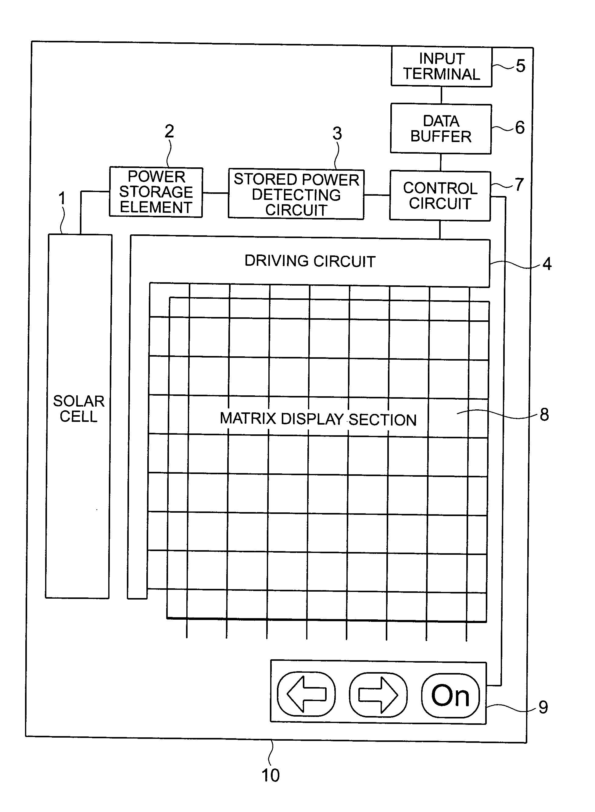
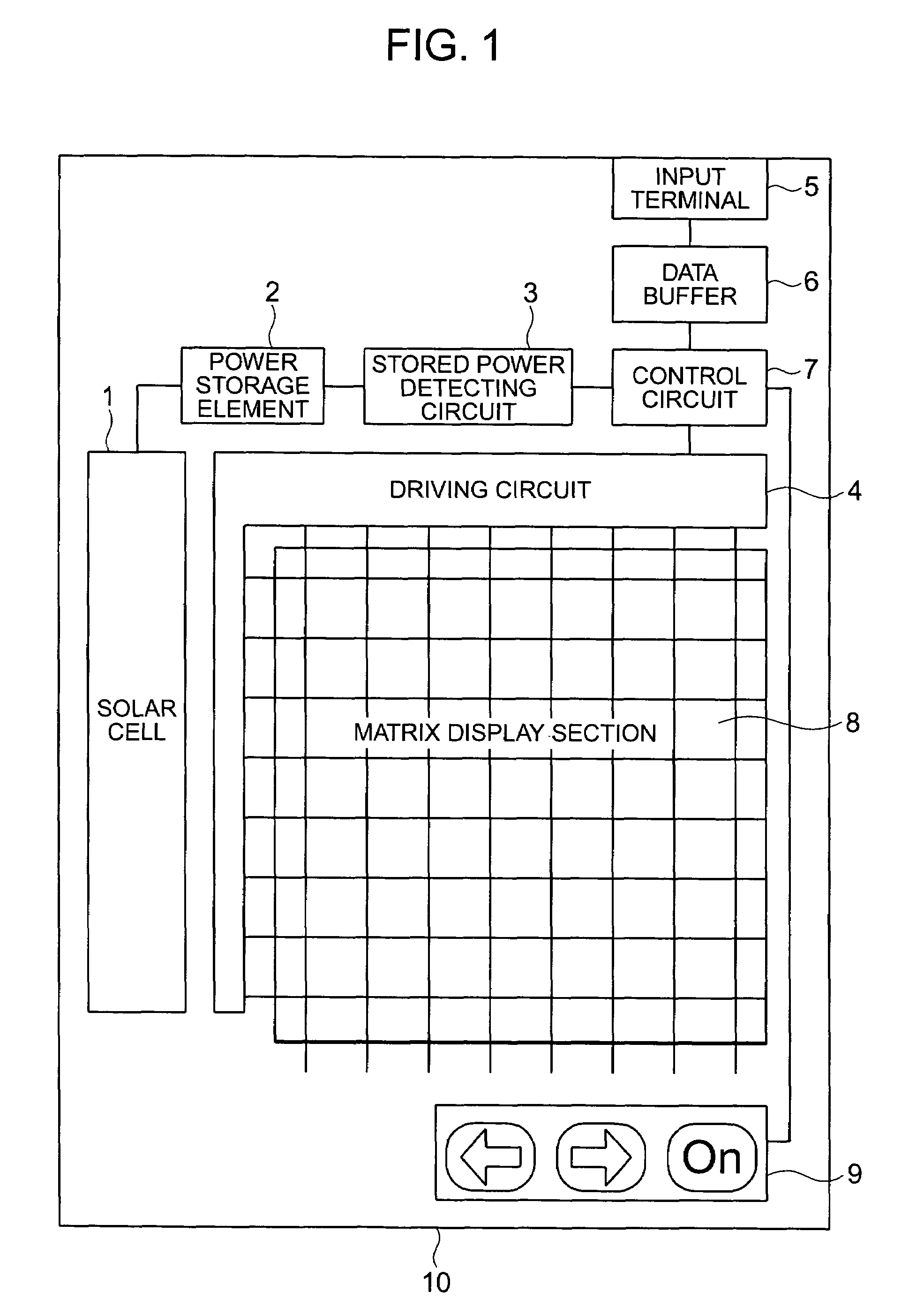
[0035]The liquid crystal display device of the invention will be described in detail with reference to the drawings of the embodiments. FIG. 1 shows a system structure diagram of the display device according to the invention. The display device of this embodiment is a reflective liquid crystal display panel. The liquid crystal display panel has a matrix display unit 8 and supplies electric power from a power supply unit, which is comprised of a solar cell 1, a power storage element 2 configuring a power storage unit and a stored power detecting circuit 3, to a driving circuit 4 via a control circuit 7 to drive the matrix display unit 8. Display data is input from an unshown external signal source through an input terminal 5 and supplied to the driving circuit 4 through a data buffer 6 and the control circuit 7. The data buffer 6 stores one frame of display data. The above components are disposed on a substrate 10, which is preferably a glass substrate, to form a sheet display device...

second embodiment

[0060]FIG. 13 is a circuit diagram of a pixel structure of the electrophoretic display panel according to the invention. In FIG. 13, the scanning wiring 81, the data wiring 82 and the thin-film transistor (TFT) 83 of the pixel are the same as those shown in FIG. 11, but a data voltage is stored in a holding capacitor 91 and connected to a display electrode 95 via an inverter which is comprised of CMOS TFTs 94a, 94b. The inverter is driven by two power supply wiring 97a, 97b. Here, an electrode common to one power wiring and the holding capacitor 91 is connected to common wiring to reduce the number of wiring. In this configuration, the written data voltage is reverse-amplified by the inverter to drive an electrophoretic element 96. Rewriting is conducted in a short time selected by a scan signal, and the response of an electrophoretic element 92 involves the movement of fine particles, so that the response does not complete. Because the element is driven for a holding period of stor...


PUM

PropertyMeasurementUnit
temperatureaaaaaaaaaa
thicknessaaaaaaaaaa
thicknessaaaaaaaaaa

Abstract

For a display device having a solar cell and a power buffer for keeping stored electric power, a display system which has a low-power drive mode, self-contained power and no need for recharging or power wiring is provided. The display system includes a solar cell using a thin-film semiconductor, a power storage element for temporarily storing the produced power, a driving circuit, a matrix display unit, a display rewrite instruction unit for inputting screen rewrite and a control circuit and starts rewriting a display when power sufficient to rewrite an image screen is stored in the solar cell. The display device having remarkable portability and no limited battery life, which controls a display mode depending on the power produced by the solar cell, can display even when power generation is low and allows self-contained power even if the storage element has a small capacity, can be obtained.

Description

BACKGROUND OF THE INVENTION[0001]The present invention relates to a display device driven by a small amount of power, and more particularly to a low-power driven electronic display device, which is a combination of a solar cell and a liquid crystal device, not requiring recharging and a method for controlling it.[0002]There have been proposed many display devices powered by a power supply using a solar cell or the like. For example, JP-A-2001-184033 discloses a display device which has a display area formed of a solar cell and a liquid crystal material having a memory property and does not need power for displaying. JP-A-5-73117 discloses a technology which connects a power buffer for storing electric power between a solar cell and a display device to drive a display circuit.[0003]A display device having a solar cell as its power supply has a considerable change in supplied electric power depending on an amount of light radiated to the solar cell. Then, when the electric power becom...

Claims


Application Information

Patent Timeline
Patent Type & Authority Patents(United States)
IPC IPC(8): G09G5/00G06F3/038G02F1/1345G02F1/00G02F1/133G09F9/00G09G3/00G09G3/20G09G3/34G09G3/36
CPCG09G3/344G09G3/3648G09G2300/0408G09G2300/0842G09G2330/021G09G2310/027G09G2310/04G09G2320/10G09G2330/02G09G2300/0857G02F1/133
Inventor MIKAMI, YOSHIROKANEKO, HIROKIMOCHIZUKI, YASUHIROKONDO, KATSUMI
Owner HITACHI LTD
Why Eureka
Try Eureka