Weld closure of through-holes in a nickel-base superalloy hollow airfoil

a superalloy and airfoil technology, applied in the field of aircraft gas turbine (jet) engines, can solve the problems of hole therethrough, reduce the cooling efficiency and overall performance of the hollow component, and the temperature of combustion gas cannot be arbitrarily high, so as to achieve good adhesion, reduce mechanical and physical properties, and practicability. good

Inactive Publication Date: 2008-01-29
GENERAL ELECTRIC CO
View PDF27 Cites 21 Cited by
  • Summary
  • Abstract
  • Description
  • Claims
  • Application Information

AI Technical Summary

Benefits of technology

[0011]The present approach provides a repair technique for through-holes in a hollow airfoil, such as those which result from the standoff spacers used in the casting of hollow-core nickel-base superalloy components. The hollow components are cast using a casting core and with standoff spacers. Any post-casting through-holes are closed by direct welding and without the use of any freestanding closure or plug element. The present approach is relatively economical to practice, and produces a final article that does not have the through-holes and also has very little, if any, reduction in mechanical and physical properties as compared with a part that did not have any through-holes. There is good adhesion between the weld alloy and the casting alloy, there is little heat-affected zone produced in the welding, and the weld alloy may be heat treated using the same temperature / time cycle as the casting alloy. The welded area is compatible with coatings such as environmental coatings and thermal barrier coatings that are applied to high-temperature components. The component having the welded holes has good environmental properties, and specifically has little if any reduction in oxidation and corrosion resistance as compared with the base metal of the component.

Problems solved by technology

The combustion-gas temperature cannot be raised to an arbitrarily high value, because of the operating temperature limits on the materials of construction of the gas turbine engine.
These standoff spacers may, however, undesirably extend through the wall of the completed hollow airfoil, leaving a hole therethrough.
Any cooling air that flows through such through-holes may reduce the cooling efficiency and the overall performance of the hollow component, if that cooling air flow out of the hollow component is not at the carefully selected locations that maximize the effect of the cooling air in improving performance.
The through-holes also potentially compromise the mechanical performance of the article, by providing a source of weakness and possible premature failure.
This approach is difficult to apply to smaller-size through-holes, due to the amount of labor involved.
These approaches either achieve only a partial solution, or the solution is expensive and laborious.
Mechanical properties are often compromised, because the welding of the inserted plug or platelet may leave a heat-affected zone that cannot be properly heat treated.

Method used


Image

  • Weld closure of through-holes in a nickel-base superalloy hollow airfoil
  • Weld closure of through-holes in a nickel-base superalloy hollow airfoil
  • Weld closure of through-holes in a nickel-base superalloy hollow airfoil

Examples


Embodiment Construction

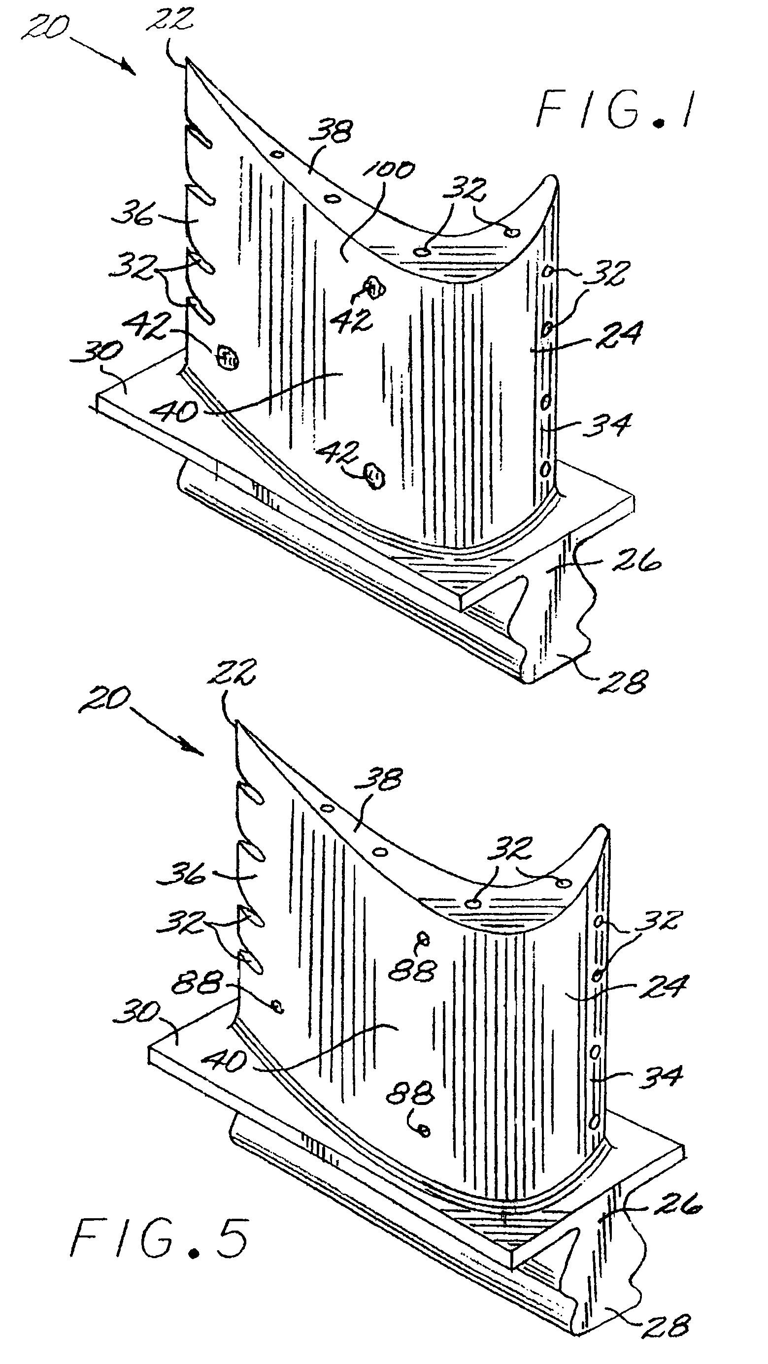
[0025]FIG. 1 depicts a cast hollow component 20, in this case a hollow gas turbine blade 22. The gas turbine blade 22 has a hollow airfoil 24 against which a flow of hot combustion gas impinges during service operation, a downwardly extending shank 26, and an attachment in the form of a dovetail 28, which attaches the gas turbine blade 22 to a gas turbine disk (not shown) of the gas turbine engine. A platform 30 extends transversely outwardly at a location between the airfoil 24, and the shank 26 and dovetail 28. The gas turbine blade 22 is hollow, so that in service cooling air may flow from an interior of the dovetail 28, which communicates with a cooling-air manifold, through an interior of the shank 26, and through an interior of the airfoil 24. The cooling air leaves the interior of the gas turbine blade 22 through carefully positioned cooling openings 32 in the leading edge 34, the trailing edge 36, and the blade tip 38, and possibly on the lateral surfaces of the airfoil 24. ...


PUM

PropertyMeasurementUnit
solidus temperatureaaaaaaaaaa
sizeaaaaaaaaaa

Abstract

A hollow airfoil is fabricated by providing a casting mold assembly including a casting mold, a casting core, and a standoff spacer that prevents the casting core from contacting the casting mold to define a casting space. A first nickel-base superalloy is cast into the casting space and solidified to form the hollow airfoil. The presence of a through-hole extending through a wall of the hollow airfoil is identified, and the through-hole is closed by welding using a second nickel-base superalloy, without using any freestanding closure element.

Description

[0001]This invention relates to the production of a cast hollow airfoil such as a gas turbine blade and, more particularly, to the closure of a hole that extends through the wall of the airfoil after the casting is complete.BACKGROUND OF THE INVENTION[0002]In an aircraft gas turbine (jet) engine, air is drawn into the front of the engine, compressed by a shaft-mounted compressor, and mixed with fuel. The mixture is burned, and the hot combustion gases are passed through a turbine mounted on the same shaft. The flow of combustion gas turns the turbine by impingement against an airfoil section of the turbine blades and vanes, which turns the shaft and provides power to the compressor and fan. In a more complex version of the gas turbine engine, the compressor and a high pressure turbine are mounted on one shaft, and the fan and low pressure turbine are mounted on a separate shaft. The hot exhaust gases flow from the back of the engine, driving it and the aircraft forward.[0003]Accordi...

Claims


Application Information

Patent Timeline
Patent Type & Authority Patents(United States)
IPC IPC(8): B22D29/00B23K31/00
CPCB23K9/0026F01D5/147F01D5/18B22C21/14B23K2201/001Y02T50/67Y10T29/49318F05D2230/21F05D2230/232B22C9/04Y02T50/676B23K2101/001Y02T50/60
Inventor GOVERN, CHRISTINEKELLY, THOMAS JOSEPHSABATO, JOSEPH GIANCARLO
Owner GENERAL ELECTRIC CO
Why Eureka
Try Eureka