Fiber-bragg grating-loop ringdown method and apparatus

a technology of ring-down loop and fiber grating, which is applied in the direction of photometry using electric radiation detectors, optical radiation measurement, instruments, etc., can solve the problems of fbg sensors, interference cavities typically coated with chemicals, and cannot survive in high temperature or chemically corroding measuring environments, etc., to achieve high accuracy/sensitivity, large measuring dynamic range, and high pressure tolerance

Inactive Publication Date: 2008-01-29
MISSISSIPPI STATE UNIVERSITY
View PDF11 Cites 36 Cited by
  • Summary
  • Abstract
  • Description
  • Claims
  • Application Information

AI Technical Summary

Benefits of technology

[0014]The present invention discloses a method of fiber grating loop ringdown (FGLRD) and apparatus including one or more fiber grating ringdown loops for temperature sensing in which a fiber Bragg-grating (FBG) or a long period grating (LPG) serves as the sensing element and is exposed to temperature changes. Conceptually different from current FBG-based temperature sensors, the temperature sensors based on the methods and apparatus as disclosed in the present invention senses temperature by measuring a time constant, namely, ringdown time. An FBG or LPG written in a section of single mode fiber, which forms a fiber grating loop, utilizes t

Problems solved by technology

The disadvantages of the FFPI sensors include the costly and complicated fabrication of the interference cavity.
Furthermore, the interference cavity, typically coated with chemicals, cannot survive in high temperature or chemically corrosive measuring environments.
The disadvantages of the current FBG sensors are low measurement accuracy and small measuring dynamic range.
The measurement accuracy is limited by both the spectral bandwidth of the FBG and the spectral resolution of an optical spectral analyzer (OSA) or spectrometer.
An OSA or spectrometer of high spectral resolution is often very expensive.
Thus far, no documentation has been discovered that indicates these CRD techniques have been utilized for physical sensor development, partially due to practicality considerations resulting from the delicate and expensive coatings/polishing of the optical cavity.
Research and development of this newly emerged FLRD technique itself is just at the starting point; measurements using the FLRD technique have been, thus far, limited to spectroscopic measurements or chemical sensing,

Method used


Image

  • Fiber-bragg grating-loop ringdown method and apparatus
  • Fiber-bragg grating-loop ringdown method and apparatus
  • Fiber-bragg grating-loop ringdown method and apparatus

Examples


example 1

Materials and Methods

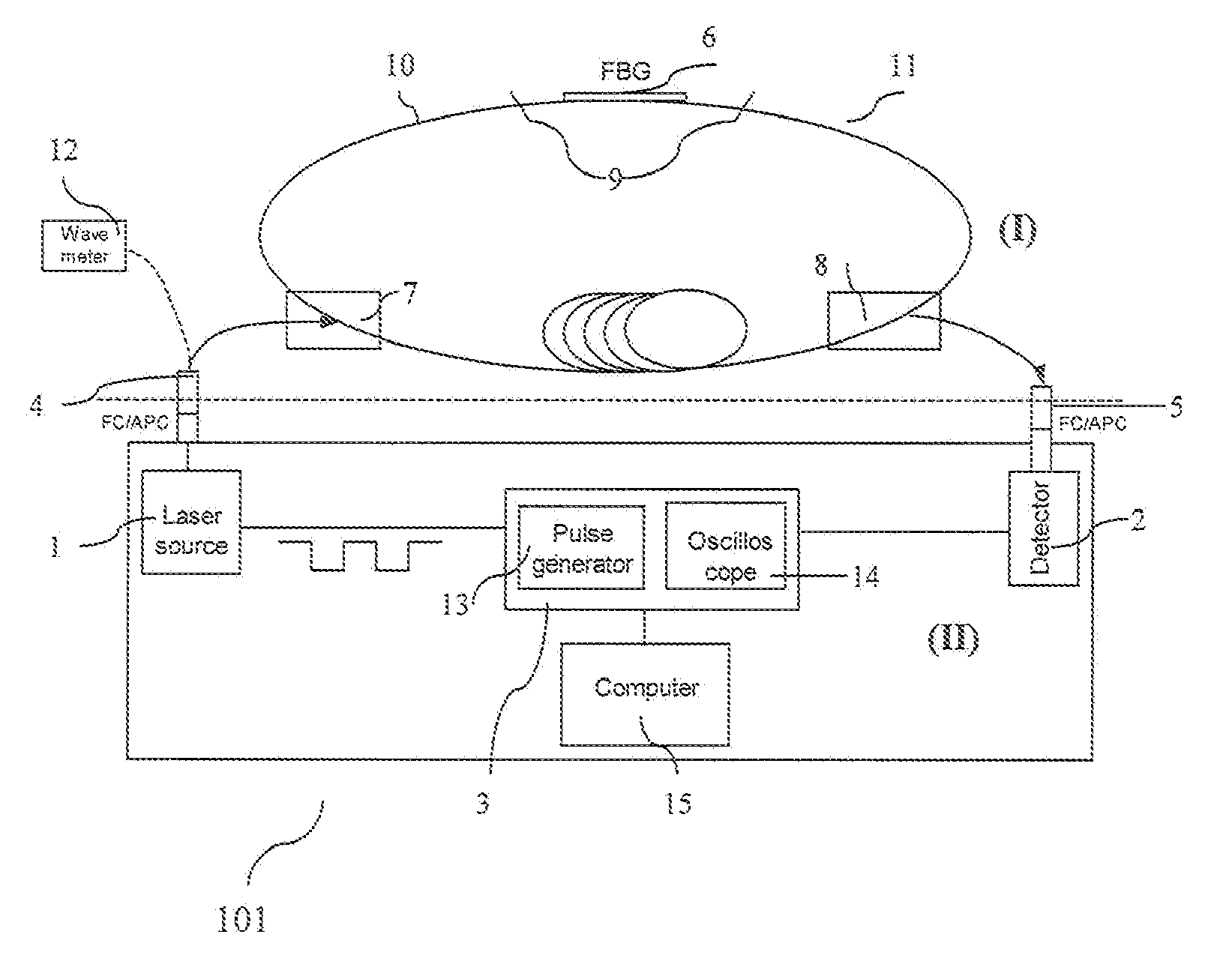
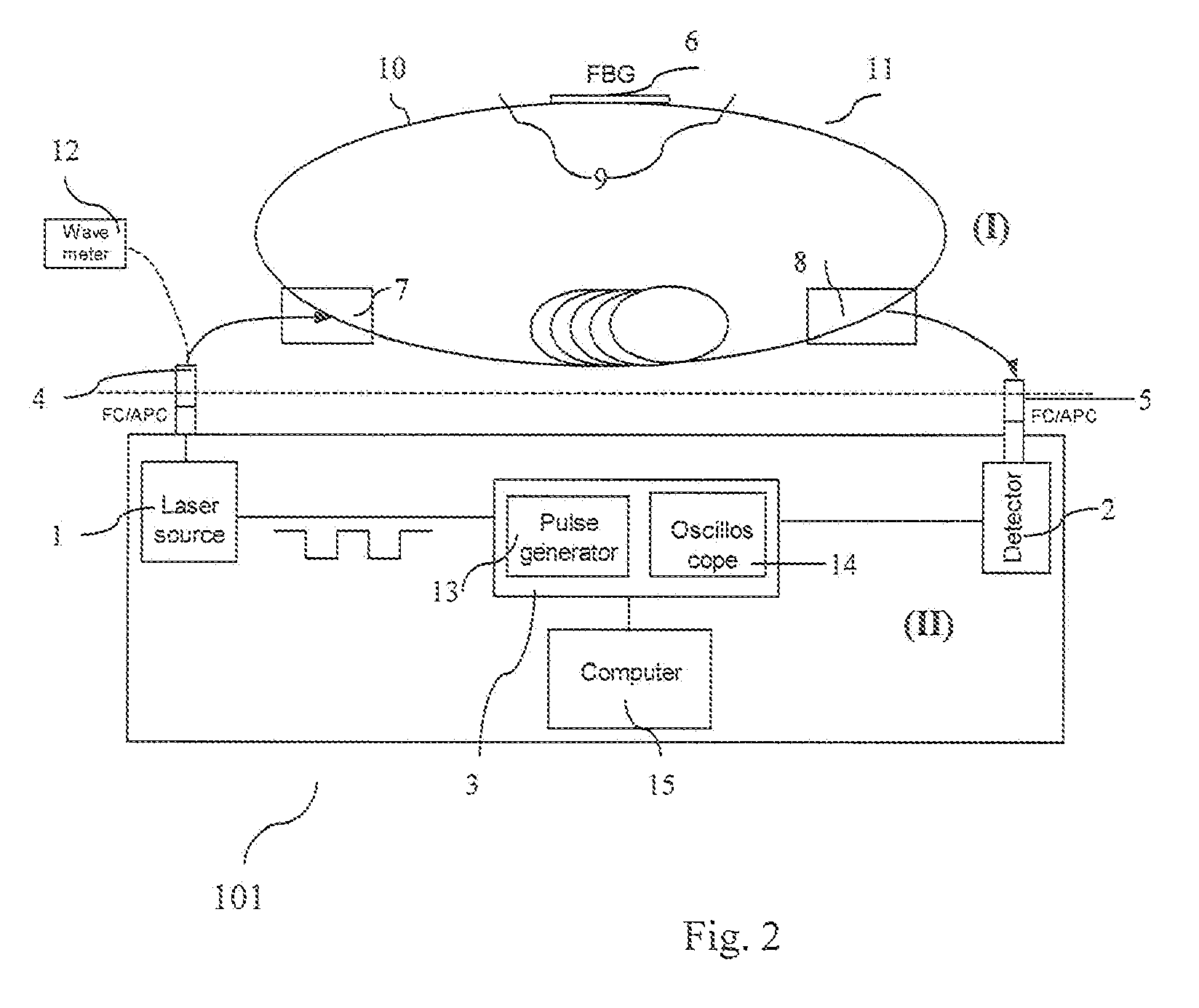
[0067]The fiber ringdown temperature sensor device, 101 (FIG. 2), consists of two major parts: a fiber loop and an electronic control portion, 3, that includes a light source, 1, and a detector, 2. These two parts are connected together through two FC / APC fiber connectors, 4, 5, as sketched in FIG. 2. The fiber loop consists of a commercial bare fiber grating, 6, (an FBG or an LPG) that is written in a section of bare fused silica single mode fiber, 9, (O / E-land), two identical 2×1 fiber couplers, 7,8 (Lightcomm Technology), and two sections of fused silica single mode fiber, 10,11 (Corning SMF 28). The quoted split ratio in the 2-leg end of the fiber couplers, 7,8, is 1:99. The two 1-leg ends of the couplers are spliced together; and the two 99% legs of the two couplers are separately spliced with the two ends of the fiber on which a grating is written to form the fiber grating loop (FITEL S321, Optical fiber Cleaver; Ericsson 925, Fusion Splicer). The light so...

example 2

Characterization of the Ringdown Behavior of Fiber Grating Loops

[0074]FIG. 3(a) shows a typical fiber Bragg grating-loop ringdown waveform, which was recorded when the laser wavelength was tuned to 1567.30 nm, corresponding to a 0.09 dB transmission loss in the FBG. The natural logarithm of the decay waveform is fitted to a line to yield a ringdown time of 4.14 μs. The good linearity of the fitting (R2=0.99) shown in FIG. 3(b) indicates that the ringdown decay waveform follows a single exponential decay. Similar evaluations of the ringdown decay behavior observed with different light transmission losses incurred in the FBG were also performed. As long as the light transmission loss that occurred in the FBG is lower than ˜1 dB (79% transmittance), a single exponential ringdown decay waveform can be obtained. Excessive optical transmission loss in the fiber loop can result in no ringdown behavior or non-single exponential decay behavior. When the laser wavelength is properly tuned in ...

example 3

Temperature Response of the FBG Ringdown Temperature Sensor (Type I)

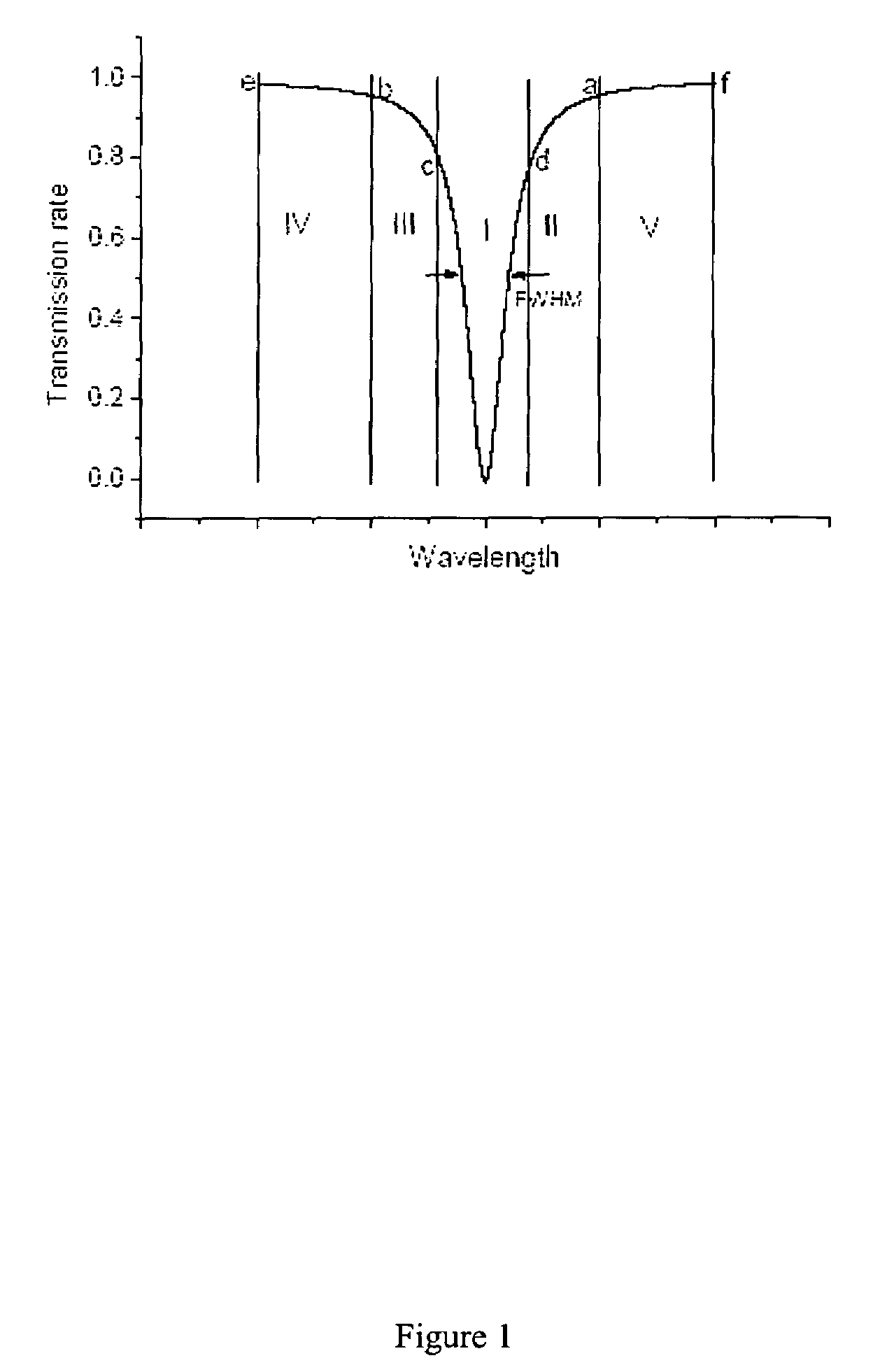
[0076]In the Type I sensor, an FBG was spliced with a single mode fiber to form a fiber Bragg grating loop and the FBG served as the sensing element. In the experiment, the laser wavelength was tuned to 1568.11 nm, which was located at the right-hand side of the spectral bandwidth curve, Zone V in FIG. 1. When the FBG temperature increases, the whole spectral response curve shifts to the longer wavelength direction and the relative position of the laser wavelength in the bandwidth curve equivalently shifts, i.e., from points a to d as illustrated in FIG. 1. The resultant transmission loss of the laser beam increases; therefore, the measured ringdown decreases. The FBG temperature control was achieved by using the electrical heating oven system which is described in the previous section. FIG. 4 shows a typical temperature response of the Type I sensor. The ringdown measurements at each temperature were performed for ...


PUM


Abstract

A device comprising a fiber grating loop ringdown (FGLRD) system of analysis is disclosed. A fiber Bragg grating (FBG) or Long-Period grating (LPG) written in a section of single mode fused silica fiber is incorporated into a fiber loop. By utilizing the wing areas of the gratings' bandwidth as a wavelength dependent attenuator of the light transmission, a fiber grating loop ringdown concept is formed. One aspect of the present invention is temperature sensing, which has been demonstrated using the disclosed device. Temperature measurements in the areas of accuracy, stability, high temperature, and dynamic range are also described.

Description

[0001]This application claims priority from U.S. Provisional Application Ser. No. 60 / 588,035 filed Jul. 15, 2004. The entirety of that provisional application is incorporated herein by reference.[0002]This invention was made with Government support under DE-FC01-04EW54600 awarded by the U.S. Department of Energy. The Government may have certain rights in the invention.BACKGROUND OF THE INVENTION[0003]1. Field of the Invention[0004]This invention relates to a method and apparatus for temperature sensing using fiber grating loop ringdown (FGLRD), in which a fiber-Bragg grating (FBG) or Long-Period grating (LPG) serves as the sensing element which determines temperature by measuring change of a time constant (i.e., ringdown time) when the element is exposed to temperature changes.[0005]2. Related Art[0006]Optical fiber sensors are superior to the conventional electrical-based sensors in many aspects: a) optical fiber sensors are inexpensive, compact, light weight, and immune to electro...

Claims


Application Information

Patent Timeline
IPC IPC(8): G01J1/04G01J1/42G01J5/08
CPCG01J5/08G01J5/0803G01J5/0821G01J5/58
Inventor WANG, CHUJI
Owner MISSISSIPPI STATE UNIVERSITY
Why Eureka
Try Eureka