Apparatus and method for elevated temperature electrospinning

a technology of electrospinning apparatus and components, which is applied in the field of relation between elevated temperature electrospinning apparatus components and the like, can solve the problems of low production rate, inability to adapt to polymers, and requiring plurality regulation

Active Publication Date: 2008-02-05
CORNELL RES FOUNDATION INC
View PDF11 Cites 79 Cited by
  • Summary
  • Abstract
  • Description
  • Claims
  • Application Information

AI Technical Summary

Benefits of technology

[0004]It has been discovered herein that apparatus and process avoiding the disadvantages of conventional solution electrospinning apparatus and process and providing useful melt electrospinning production of polymer and nanocomposite fibers / non-wovens and useful solution electrospinning apparatus and processes for operation on polymers which are not dissolvable in acceptable solvents at room temperature, can be provided by relying on unique heating apparatus / process.
[0005]In one embodiment herein, the invention is directed to apparatus for elevated temperature production of non-woven fabric from thermoplastic polymer or thermoplastic polymer nanoclay nanocomposite, neat or in solution and requiring elevated temperature for dissolving in an acceptable solvent, said apparatus comprising a resistance heater for melting the polymer or nanocomposite or maintaining the polymer or nanocomposite in solution in acceptable solvent; a pump upstream of or containing the resistance heater for dispensing said melted polymer or nanocomposite or solution; a droplet forming passageway for receiving said polymer or nanocomposite melt or solution and having one or more outlet orifices for providing one or more droplets of melted polymer or nanocomposite or solution at the one or more outlet orifices; a guiding chamber having an inlet side in fluid communication with the outlet orifice(s); a collection surface at the rear side of the guiding chamber for receiving elongated fibers of polymer or nanocomposite and collecting them as a non-woven fabric; and a high voltage source in electrical communication with the droplet forming passageway to provide an electric charge in the droplet(s) emitting therefrom to overcome the surface tension of a droplet to produce a jet of melted polymer or nanocomposite or solution in the guiding chamber giving rise to unstable flow through the guiding chamber to the collection surface manifested by a series of electrically induced bending instabilities and flashing off of any solvent during passage of polymer or nanocomposite to the collection surface and production of elongated fibers of polymer or nanocomposite and deposit of these on the collection surface so as to form the non-woven fabric. In the apparatus preferably, the electrical communication of the high voltage source is shielded from the resistance heater to prevent induced voltage in the resistance heater and a temperature modulator is provided for the guiding chamber to adjust cooling of the fiber being formed to provide against premature solidification and to provide against induction of relaxation of molecular orientation, and to potentiate flashing off of any solvent, without affecting the bending instabilities causing fiber elongation.

Problems solved by technology

Current solution electrospinning apparatus and processes have the disadvantages of requiring a dissolving step, of requiring solvent recovery and disposal or complete recycling if the process is to be environmentally friendly, of having low production rates because of the dissolving and solvent recovery / recycling steps detracting from obtaining high throughput, of not being adaptable to polymers such as polyethylene, polypropylene, polyethylene terephthalate and polybutylene terephthalate, which are not dissolvable in acceptable solvents at room temperature, of requiring regulation of a plurality of parameters to adjust molecular properties and solidification and of requiring apparatus not readily provided by adaption of conventional existing facilities for fiber / non-woven production for most polymers since these are based on melt treatment.
Moreover, no attempts have been made to provide solution electrospinning apparatus and processes which are suitable for operation on polymers which are not dissolvable in acceptable solvents at room temperature.

Method used


Image

  • Apparatus and method for elevated temperature electrospinning
  • Apparatus and method for elevated temperature electrospinning

Examples


working example i

Effect of Flow Rate, Distance and Applied Voltage on Fiber Diameter

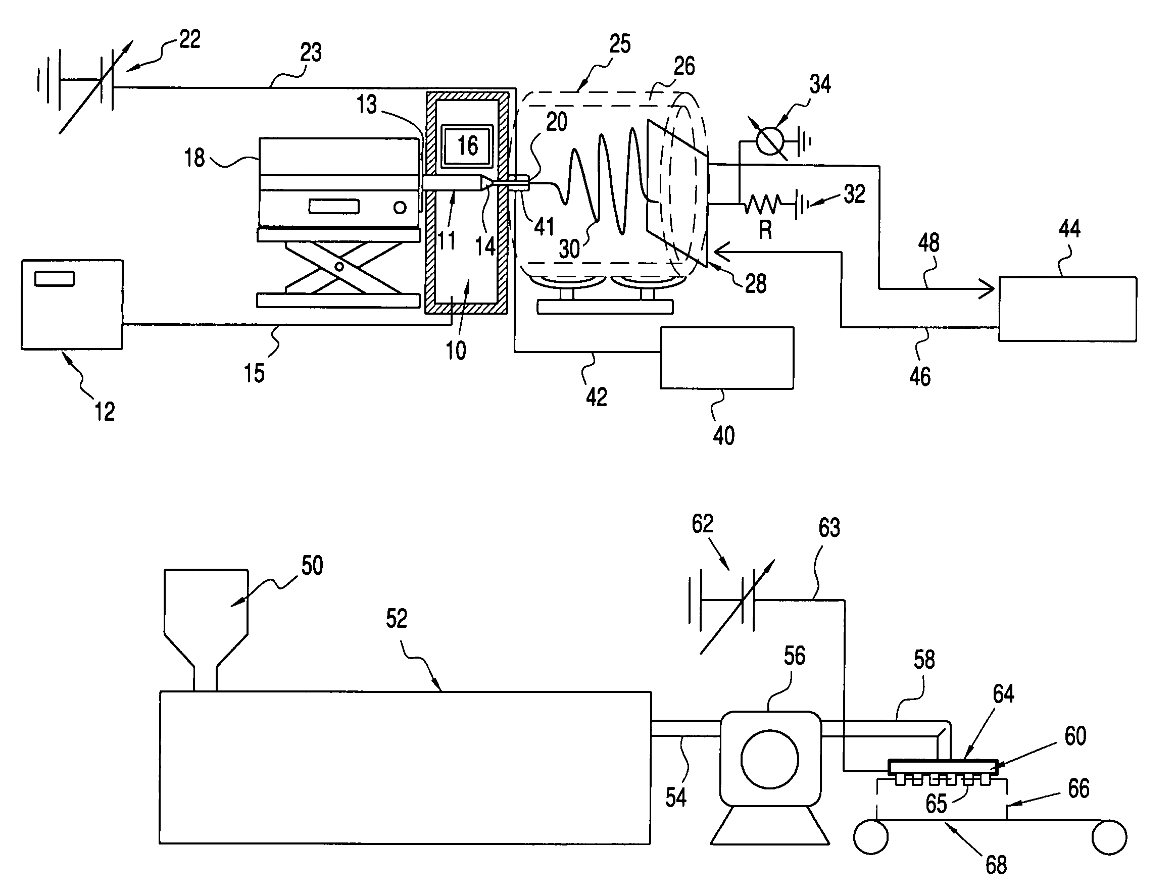
[0066]The nozzle diameter was 0.84 mm. The temperatures used were T2=220° C., T3=100° C. and T4=60° C. Flow rates, distance between nozzle orifice and collector, voltage applied to the nozzle, are varied and results in terms of fiber diameter in μm are given in Table 1 below.

[0067]

TABLE 1VoltageFlow RateDistance10 kV15 kV20 kV0.01 / ml / min3″3.23 ± 0.675.34 ± 0.6714.29 ± 2.83 6″7.65 ± 1.455.53 ± 0.918.21 ± 1.770.005 ml / min3″5.74 ± 1.454.85 ± 1.008.83 ± 1.666″6.67 ± 1.104.70 ± 0.944.46 ± 2.19

[0068]Except for one case with 10 kV and 3 inches, decreasing flow rate decreases the fiber diameter, possibly due to the increase in residence time (and thus, lower exposure to whipping motion).

[0069]At higher voltage setting (20 kV), the straight stable jet tends to extend longer and thus the whipping region is shortened, which leads to thicker fibers. Increasing the distance (from nozzle tip to collector) and thus increasing the w...

working example ii

Effect of Nozzle Temperature (T2) on Fiber Diameter

[0070]The nozzle diameter was 0.84 mm. The temperatures used were T3=100° C. and T4=60°; T2 was varied. Flow rate was 0.01 ml / min. Voltage was 15 kV. Distance between the nozzle and collector was 3 inches. The results are given in Table 2 below:

[0071]

TABLE 2T2Fiber DiameterStandard(° C.)(μm)dev. (μm)2155.580.542256.172.191906.850.461609.491.131755.761.122055.361.70

The results show that if T2 is too high or too low, the fiber diameter tends to get thicker. Too low temperature freezes up the filament and thus less whipping motion can be induced. Too high temperature decreases the viscosity of the jet, and eventually continuous production of fiber would not be possible. High temperature (225° C.) also leads to poor size distribution. From the data it appears that T2 of above 215 to 220° C. leads to small fiber diameter with uniform size distribution.

working example iii

Effect of (T3) on Fiber Diameter

[0072]The nozzle diameter was 0.84 mm. The temperatures used were T2=220° C. and T4=60°; T3 was varied. Flow rate was 0.01 ml / min. Voltage was 15 kV, and distance between the nozzle and collector was 3 inches. The results are given in Table 3 below:

[0073]

TABLE 3T3Fiber DiameterStandard(° C.)(μm)dev. (μm)2515.02.541005.340.67

[0074]The results show that increasing T3 decreases fiber diameter, and with T3=100° C., uniform size distribution is obtained.


PUM

PropertyMeasurementUnit
temperatureaaaaaaaaaa
temperaturesaaaaaaaaaa

Abstract

Elevated temperature electrospinning apparatus comprises a pump upstream of or containing a resistance heater, means to shield applied electrostatic field from the resistance heater, and a temperature modulator for modulating temperature in the spinning region.

Description

CROSS-REFERENCE TO RELATED APPLICATIONS[0001]This application claims the benefit of U.S. Provisional Patent Application No. 60 / 583,358 filed Jun. 29, 2004, the whole of which is incorporated herein by reference.TECHNICAL FIELD[0002]This invention is directed to relationship of elevated temperature electrospinning apparatus components, including isolation of the chamber supplying heat for melting and temperature control in the spinning region.BACKGROUND OF THE INVENTION[0003]Fibers with diameters less than a micron can be formed using electrospinning processes where a droplet of polymer solution or melt is elongated by a strong electrical field. The resulting fibers are collected as non-woven mats with extremely large surface to volume ratio; which are useful for various applications including filtration. Most previous studies on electrospinning have focused on fibers from polymer solutions, i.e., are directed to solution electrospinning. Current solution electrospinning apparatus an...

Claims


Application Information

Patent Timeline
Patent Type & Authority Patents(United States)
IPC IPC(8): B29B13/08A01J21/02D01D5/00
CPCD01D5/0023D01D5/0038D01D5/084D01D5/0007D01F6/625D04H3/02D01F1/10Y10S425/217
Inventor JOO, YONG LAKZHOU, HUAJUN
Owner CORNELL RES FOUNDATION INC
Why Eureka
Try Eureka