
Advanced contaminate treatment system

a technology of contaminant treatment and advanced technology, applied in the direction of gas treatment, isotope separation, water/sludge/sewage treatment, etc., can solve the problems of high cost, high capital cost, and inability to achieve acf to concentrate btex, etc., to achieve the effect of increasing costs, increasing capital costs, and high flow rate of wastewater

Active Publication Date: 2008-02-05
PURIFICS ENVIRONMENTAL TECH
View PDF9 Cites 27 Cited by
  • Summary
  • Abstract
  • Description
  • Claims
  • Application Information

AI Technical Summary

Benefits of technology

This approach enables cost-effective, high-volume decontamination of VOCs at high flow rates without explosive hazards, reduces capital costs, and allows for complete VOC recovery and reuse, maintaining a closed-loop system with minimal external inputs and no greenhouse gas emissions.

Problems solved by technology

Through the disclosed approaches, several deficiencies not addressed by conventional systems may be overcome, such as avoiding explosive hazards, the fact that certain VOCs, such as Benzene, Toluene, EthylBenzene and Xylene (BTEX), are typically too dilute for cost effective use in a thermal oxidizer, the fact that ‘high boilers’ prevent the use of ambient pressure steam activated carbon fiber (ACF) bed desorption, and that biological-based decontamination systems typically do not function well, if at all, in cold environments.
Then, with the high boilers issue, using ACF to concentrate BTEX can only typically be accomplished if the desorption temperature exceeds the minimum boiling temperature of 140° C. Direct steam is not usually feasible due to economic constraints and hydrolysis degradation of ACF.
In direct steam regeneration of ACF beds, to obtain the high boil temperature of 140° C. the large ACF container would have to be a pressure vessel, which typically has a high cost.

Method used


Image

  • Advanced contaminate treatment system
  • Advanced contaminate treatment system
  • Advanced contaminate treatment system

Examples


Embodiment Construction

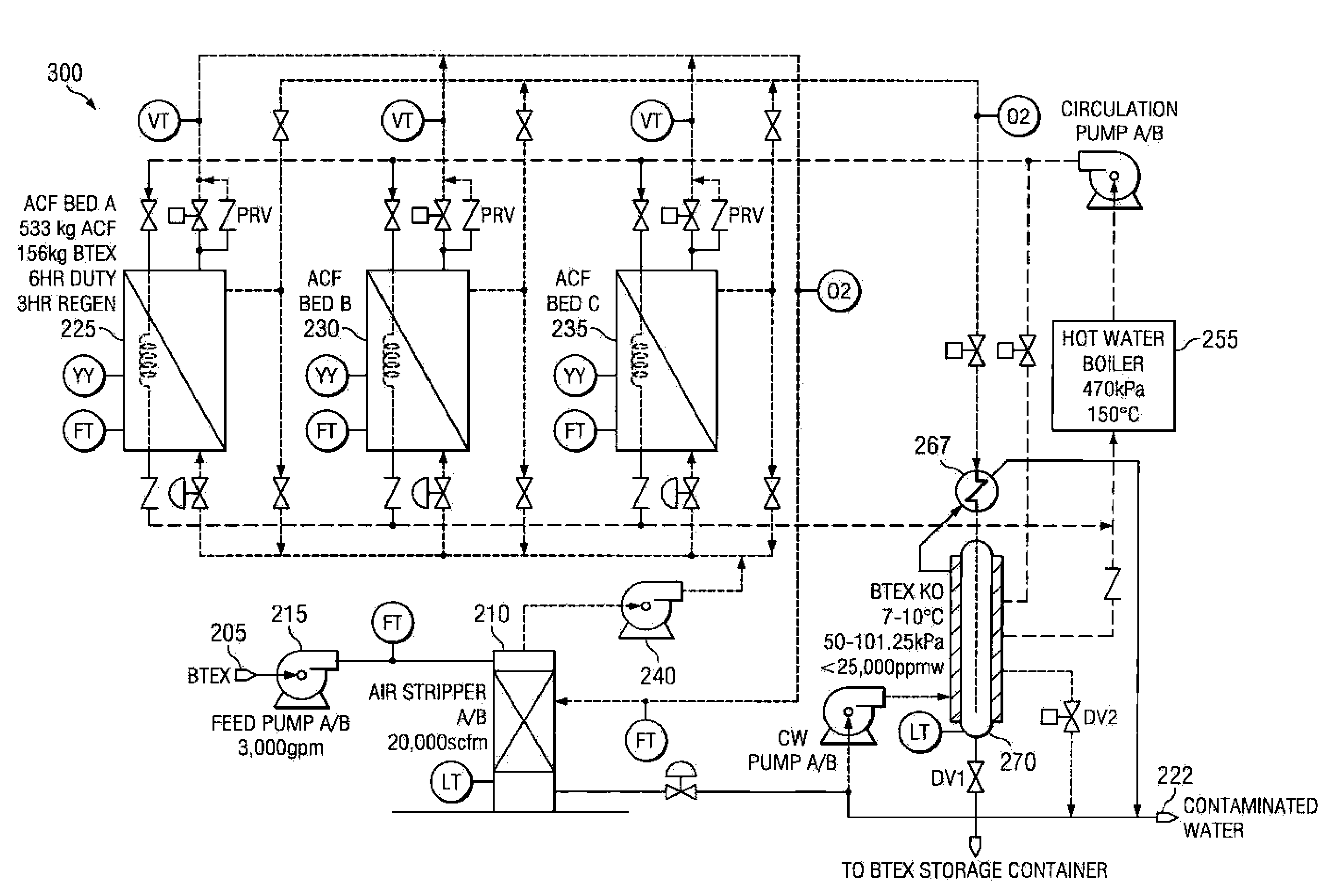
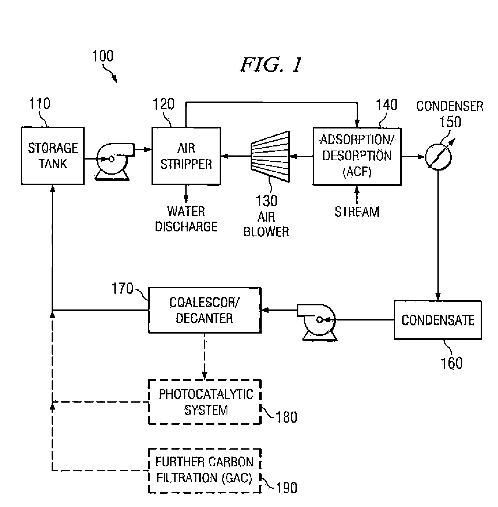
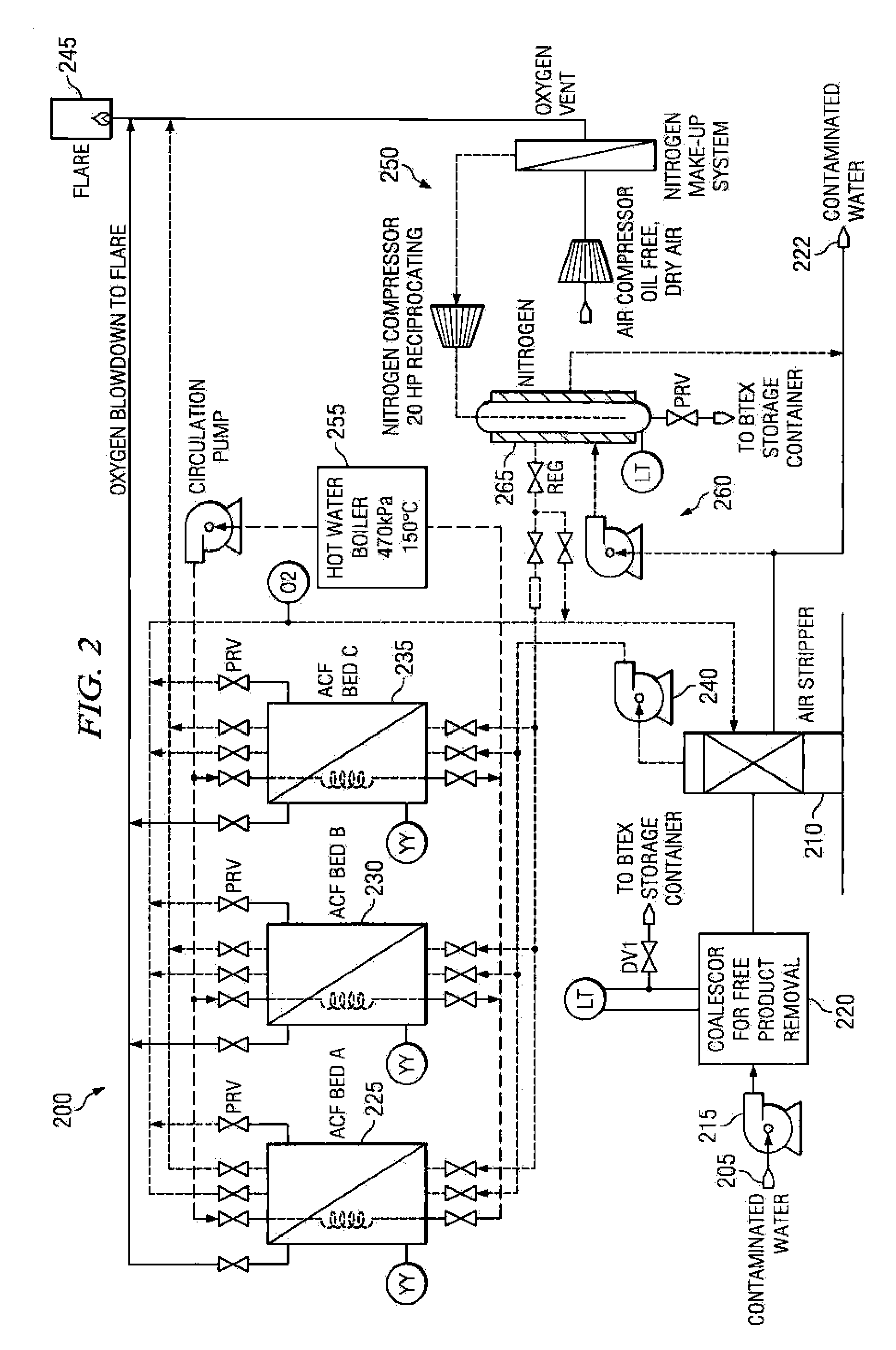
[0015]Referring to FIG. 1, illustrated is one embodiment of a high flow treatment system 100 according to the principles disclosed herein. The system 100 includes a storage tank 110 where contaminated media may be held prior to entering the system 100 for decontamination. Examples of contaminated media may include seawater, such as that found in ballast applications for large ships, as well as fresh water reservoirs in need of decontamination. Such fresh water applications may be for decontaminating brackish water (e.g., where seawater has contaminated a fresh water supply), or for ground water suffering from high alkalinity (e.g., water residing proximate limestone deposits). Thus, the disclosed techniques are effective for treating organic contaminants in wastewater in various applications where there is a significant flow rate of wastewater to be decontaminated, and even where there are hydroxyl radical scavengers (e.g., alkalinity or chloride ions) in the contaminated media. Mor...


PUM

PropertyMeasurementUnit
temperatureaaaaaaaaaa
boil temperatureaaaaaaaaaa
boiling temperatureaaaaaaaaaa

Abstract

Decontamination systems and methods are disclosed. In one embodiment, a system comprises a first adsorption / desorption subsystem that is configured to receive a contaminated gaseous solution and remove substantially all of the contaminants from the contaminated gaseous solution during an adsorption cycle, while a second subsystem is configured to purge captured contaminants during a desorption cycle. An evacuator is configured to drive potentially flammable gas compositions from the subsystem operating in a desorption cycle back into the system such that potentially flammable gas compositions are purged from the subsystem operating in the desorption cycle at the beginning of the desorption cycle. A heat source is configured to heat contaminants adsorbed in the adsorption / desorption subsystems to remove the contaminants from the adsorption / desorption subsystems in a gaseous state during their respective desorption cycle.

Description

CROSS-REFERENCE TO RELATED APPLICATION[0001]This Application claims the benefit of U.S. Provisional Application Ser. No. 60 / 539,559, filed on Jan. 27, 2004, and entitled “Advanced Contaminant Treatment System” and U.S. Provisional Application Ser. No. 60 / 598,302, filed on Aug. 3, 2004, and entitled “Phase Extraction Technology”, both of which are commonly assigned with the present Application and incorporated herein by reference in their entirety for all purposes.TECHNICAL FIELD[0002]Disclosed embodiments herein relate generally to contamination treatment systems, and more particularly to advanced contaminant treatment systems and methods for cost-effective decontaminating of media at high flow rates.BACKGROUND[0003]Various industrial processes produce pollutant vapors and gases. These vapors and gases should be treated to avoid release of pollutants into the atmosphere. Other industries produce gases, which include end products, e.g., paint solvents. Recapture of end product increa...

Claims


Application Information

Patent Timeline
Patent Type & Authority Patents(United States)
IPC IPC(8): B01D53/04B01D5/00B01D53/02B01D53/047B01D53/38B01D53/75B01J35/00C07D213/04
CPCB01D5/0054B01D53/0462B01D53/38B01D53/75C02F1/20B01D53/053B01D2253/102B01D2256/12B01D2257/102B01D2257/104B01D2257/708B01D2259/40001B01D2259/40056B01D2259/4009B01D2259/403C02F1/04C02F1/283C02F1/40C02F2101/322C02F2103/18C02F2305/10
Inventor BUTTERS, BRIAN E.POWELL, ANTHONY L.PEARCE, JOHN DOUGLASMURDOCK, MATTHEW BRIAN FREDERICK
Owner PURIFICS ENVIRONMENTAL TECH
Learn More