Optical waveform monitor apparatus and oscilloscope

a monitor and optical waveform technology, applied in the field of optical sampling apparatus, can solve the problems of inability to obtain satisfactory time resolution in time, limited time resolution for detection of signal intensity, and inability to detect signal intensity in time, etc., and achieve high linearity and high generation efficiency

Inactive Publication Date: 2008-02-05
FUJITSU LTD
View PDF13 Cites 3 Cited by
  • Summary
  • Abstract
  • Description
  • Claims
  • Application Information

AI Technical Summary

Benefits of technology

[0026]It is also desired that the optical sampling apparatus according to the present invention further includes an optical fiber as nonlinear optical medium, and the optical fiber substantially matches the wavelength of the pumping light in wavelength of zero variance over the necessary length required to generate the four optical wave mixing with sufficient efficiency.
[0028]It is also desired that the optical fiber is a highly linear optical fiber having high generation efficiency of the third-order nonlinear optical effect per unit length by doping the core with germanium, bismuth, etc. and controlling the refractive index ratio between the core and cladding in the optical sampling apparatus according to the present invention.

Problems solved by technology

Since these processes are electrically performed, the time resolution for detection of the signal intensity of a transmission signal is restricted by the operation speed of electronics.
In this case, the time resolution for detection of the signal intensity is restricted by the operation speed of the electronics.
Therefore, satisfactory time resolution cannot be obtained in the time waveform observation of not only signal light having the transmission speed of 160 Gbit / s, but also signal light having the transmission signal of 10˜40 Gbit / s.
As a result, a time resolution limit is proposed.
However, the generation efficiency of the sum (or difference) frequency light generated by the second-order nonlinear optical effect is very small.
Therefore, there has the problem that a very strong power of sampling pulse light has to be input to the nonlinear optical crystal so as to generate the sum (or difference) frequency light having sufficiently high intensity to detect the time waveform of signal light.
Additionally, since the S / N ratio (signal-to-noise ratio) of the sum (or difference) frequency light generated through a nonlinear optical crystal is considerably degraded, the noise is amplified when a signal is amplified based on the sum (or difference) frequency light, thereby failing in detecting the time waveform of the signal light with high precision.

Method used


Image

  • Optical waveform monitor apparatus and oscilloscope
  • Optical waveform monitor apparatus and oscilloscope
  • Optical waveform monitor apparatus and oscilloscope

Examples


first embodiment

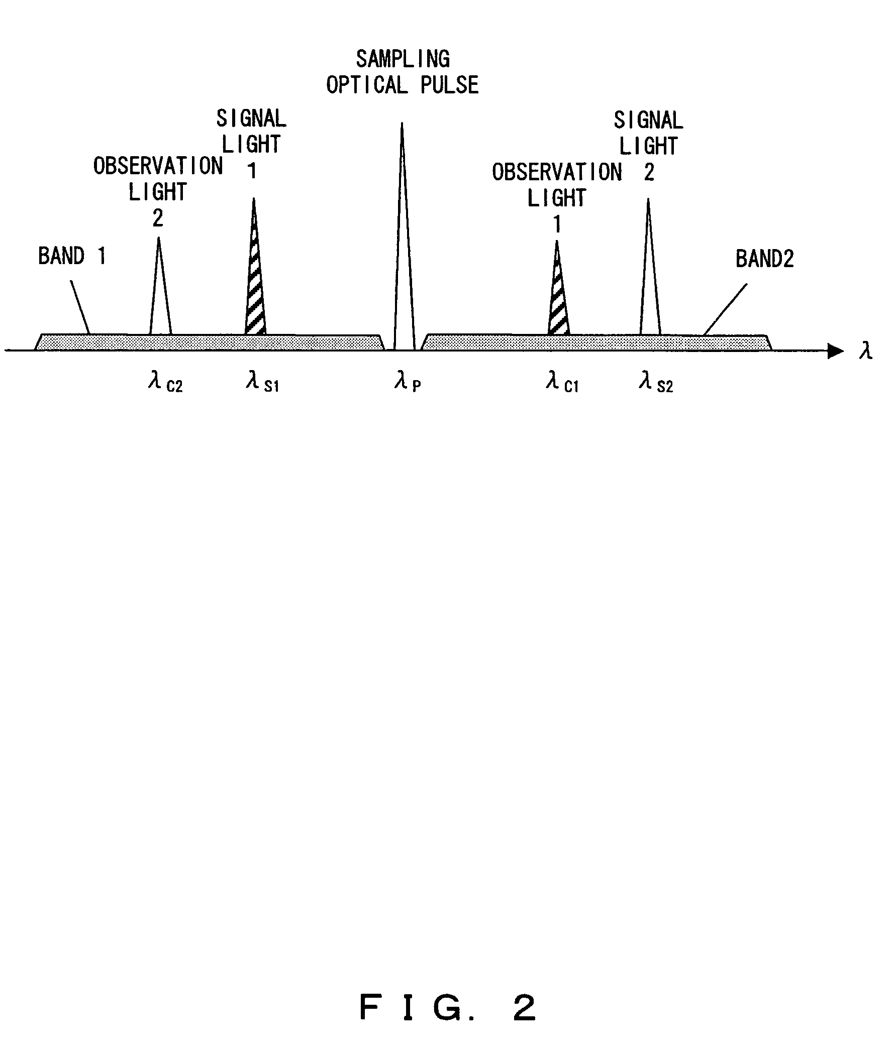
[0062]FIG. 2 shows the first wavelength arrangement of the optical sampling according to the present invention.

[0063]Assume that there are two wavelength bands which can be observed. For example, they are a visible light band and a infrared band, or a C-band and an L-band for optical communications.

[0064]When the signal light of a wavelength contained in one of the above-mentioned two bands is observed, in the first case as shown in FIG. 2, the sampling optical pulse is prepared around the center between the two wavelength band, the signal light and the sampling optical pulse are input to the nonlinear optical medium to be wavelength-converted into another wavelength band, and the wavelength converted light is observed, thereby successfully performing a waveform observation.

[0065]When the optical AND circuit uses the nonlinear optical wave mixing such as the four optical wave mixing (FWM), three optical wave mixing (TWM), etc., the above-mentioned wavelength arrangement is used. In ...

second embodiment

[0068]FIGS. 3 and 4 show second wavelength arrangement of the optical sampling in the present invention.

[0069]As the second embodiment of the present invention, an optical Kerr switch by the mutual phase modulation (XPM) in the optical fiber and an optical gate such as a NOLM are used as the nonlinear optical effect for the optical AND circuit. In this case, as shown in FIG. 3, the signal light and the sampling optical pulse are arranged in different wavelength bands. As shown in FIG. 4, signal light and converted light having the same wavelength as the signal light can be observed.

[0070]In this case, by preparing the sampling optical pulse in a wavelength b and different from the wavelength band of the signal light, the observation light can be generated in the same wavelength band as the signal light. Therefore, the observation light and the signal light can be observed in the ultrafast observation using the same measuring tools.

[0071]Described below is the practical method for re...

third embodiment

[0072]FIG. 5 is an explanatory view showing an example of the configuration of the optical gate using the four optical wave mixing in the optical fiber according to the present invention.

[0073]In the present embodiment, an optical fiber is used as a device for generating a nonlinear optical effect. The optical fiber to be used is assumed to be available in the four optical wave mixing over two bands using the pumping light of the wavelength λp.

[0074]A preferred example of the above-mentioned optical fiber can be optical fiber with an improved nonlinear optical effect such as highly-nonlinear fiber, photonic crystal fiber, bismuth substitute fiber, etc. A nonlinear device other than the optical fiber can be a semiconductor optical amplifier and a quantization dot optical amplifier for the four optical wave mixing, LiNbO3 (periodically poled LN (PPLN)) of the pseudo phase consistent structure for the three optical wave mixing, etc.

[0075]To realize the four optical wave mixing over a s...


PUM

PropertyMeasurementUnit
frequencyaaaaaaaaaa
response timeaaaaaaaaaa
lengthaaaaaaaaaa

Abstract

A measured optical pulse and a sampling optical pulse having different wavelengths are input to a nonlinear optical effect, that is, (i) a nonlinear optical medium generating four optical wave mixing or three optical wave mixing, and the optical intensity of the wavelength converted light generated by the four optical wave mixing or four optical wave mixing generated in a common portion in time of the two optical pulses is detected, thereby observing the waveform of a measured light, or (ii) a nonlinear optical medium generating mutual phase modulation which generates mutual phase modulation, and the optical intensity of converted light switched using a phase shift by mutual phase modulation generated in a common portion in time is detected, thereby observing the waveform of measured light.

Description

BACKGROUND OF THE INVENTION[0001]1. Field of the Invention[0002]The present invention relates to an optical sampling apparatus for measuring a time waveform of signal light with high precision, and an optical sampling oscilloscope forming part of the optical sampling apparatus.[0003]2. Description of the Related Art[0004]Conventionally, a digital (sampling) oscilloscope has become commercially practical and widespread as an apparatus for observing the time waveform of a transmission signal.[0005]In the digital oscilloscope, the signal intensity of the electric signal which changes in intensity with time is detected at predetermined time intervals, and signal processing for joining in time the signal intensity of the detected electric signal is performed, and the joined time waveform is, for example, displayed on the display screen. Since these processes are electrically performed, the time resolution for detection of the signal intensity of a transmission signal is restricted by the...

Claims


Application Information

Patent Timeline
Patent Type & Authority Patents(United States)
IPC IPC(8): G02F1/35G02F2/02G01J11/00G01R13/40G02F1/377H04B10/07H04B10/079H04B10/29
CPCG01J11/00
Inventor WATANABE, SHIGEKI
Owner FUJITSU LTD
Why Eureka
Try Eureka