Method and apparatus for maximizing radiation shielding during cask transfer procedures

a radiation shielding and cask transfer technology, applied in nuclear engineering, nuclear elements, greenhouse gas reduction, etc., can solve the problems of high radioactivity of spent nuclear fuel, increased radiation shielding costs, and increased radiation shielding costs, and achieves the effect of reducing the radiation shielding of spent nuclear fuel and reducing the radiation exposure of spent nuclear fuel

Inactive Publication Date: 2008-02-12
HOLTEC INT
View PDF42 Cites 17 Cited by
  • Summary
  • Abstract
  • Description
  • Claims
  • Application Information

AI Technical Summary

Benefits of technology

[0015]It is an object of the present invention to provide an apparatus that can provide the maximum amount of radiation shielding during all stages of a spent nuclear fuel transfer procedure, even when the weight of the apparatus's payload is varied.
[0016]Another object of the present invention is to provide an apparatus for transferring spent nuclear fuel, the weight of which can be easily and quickly varied in order to maximize the amount of radiation shielding for a varied payload without substantially increasing the transfer procedure cycle time.
[0017]Yet another object of the present invention is to provide an apparatus for transferring spent nuclear fuel that can be lifted and transported by a low-capacity crane and still provide adequate radiation shielding during all stages of the transfer procedure.
[0018]Still another object of the present invention is provide a method of transferring a canister of spent nuclear fuel that provides the maximum amount of radiation shielding during all stages of the transfer procedure, even when the weight of the apparatus's payload is varied.
[0024]In another aspect, the invention is a method of transferring spent nuclear fuel from a pool comprising submersing an apparatus having a jacket, a cavity, and a canister within the cavity, for receiving spent nuclear fuel into a pool so that the canister fills with pool water, wherein the jacket is empty and hermetically sealed; placing spent nuclear fuel into the canister; lifting the transfer cask from the pool; placing the transfer cask in a staging area; filling the jacket with neutron absorbing liquid; draining the pool water from the canister, thereby reducing the weight of the transfer cask; and lifting the apparatus from the staging area.

Problems solved by technology

Upon depletion and subsequent removal, spent nuclear fuel is still highly radioactive and produces considerable heat, requiring that great care be taken in its packaging, transporting, and storing.
Specifically, spent nuclear fuel emits extremely dangerous neutrons and gamma photons.
However, a canister alone does not provide adequate containment of the neutrons and gamma photons emitted by the spent nuclear fuel contained therein.
As such, a loaded canister cannot be further transported from the storage pool without some additional radiation shielding.
First, the gamma radiation emitted by spent nuclear fuel is blocked by placing mass in its way, the greater the density and thickness of the blocking mass, the more effective the attenuation of the gamma radiation.
Second, the neutrons emitted by spent nuclear fuel are blocked by placing a material containing hydrogen atoms in their path.
As a result of maximizing the thickness of the gamma and neutron absorbing materials, the weight and size of storage casks often cause problems associated with lifting and handling.
A common problem is that storage casks are often too heavy for the capacity of most nuclear power plant cranes and as such cannot be lifted.
Another common problem is that storage casks are too large to be placed in storage pools.
However, increasing the density and / or thickness of the materials used to make the transfer cask also results in the weight of the cask being increased.
However, the allowable weight of a transfer cask is limited by the lifting capacity of the plant's crane (or other lifting equipment).
The transfer cask is then constructed using this permissible weight as a design limitation.
However, a heavier transfer cask can not be used throughout the entire transport procedure because of the fact that the combined weight of the heavier transfer cask and its payload would exceed the rated lifting capacity of the crane during the step of initially lifting the transfer cask from the storage pool.
Thus, the maximum amount of radiation shielding is not provided throughout every step of the transfer and dry storage procedure.
While it is possible to transfer the canister of spent nuclear fuel to a heavier transfer cask once the payload is lightened from dewatering, this would take added time, money, effort, space, and equipment.
An additional transfer would also increase the amount of radiation exposure to personnel and the chances of a handling mishap.

Method used


Image

  • Method and apparatus for maximizing radiation shielding during cask transfer procedures
  • Method and apparatus for maximizing radiation shielding during cask transfer procedures
  • Method and apparatus for maximizing radiation shielding during cask transfer procedures

Examples


Embodiment Construction

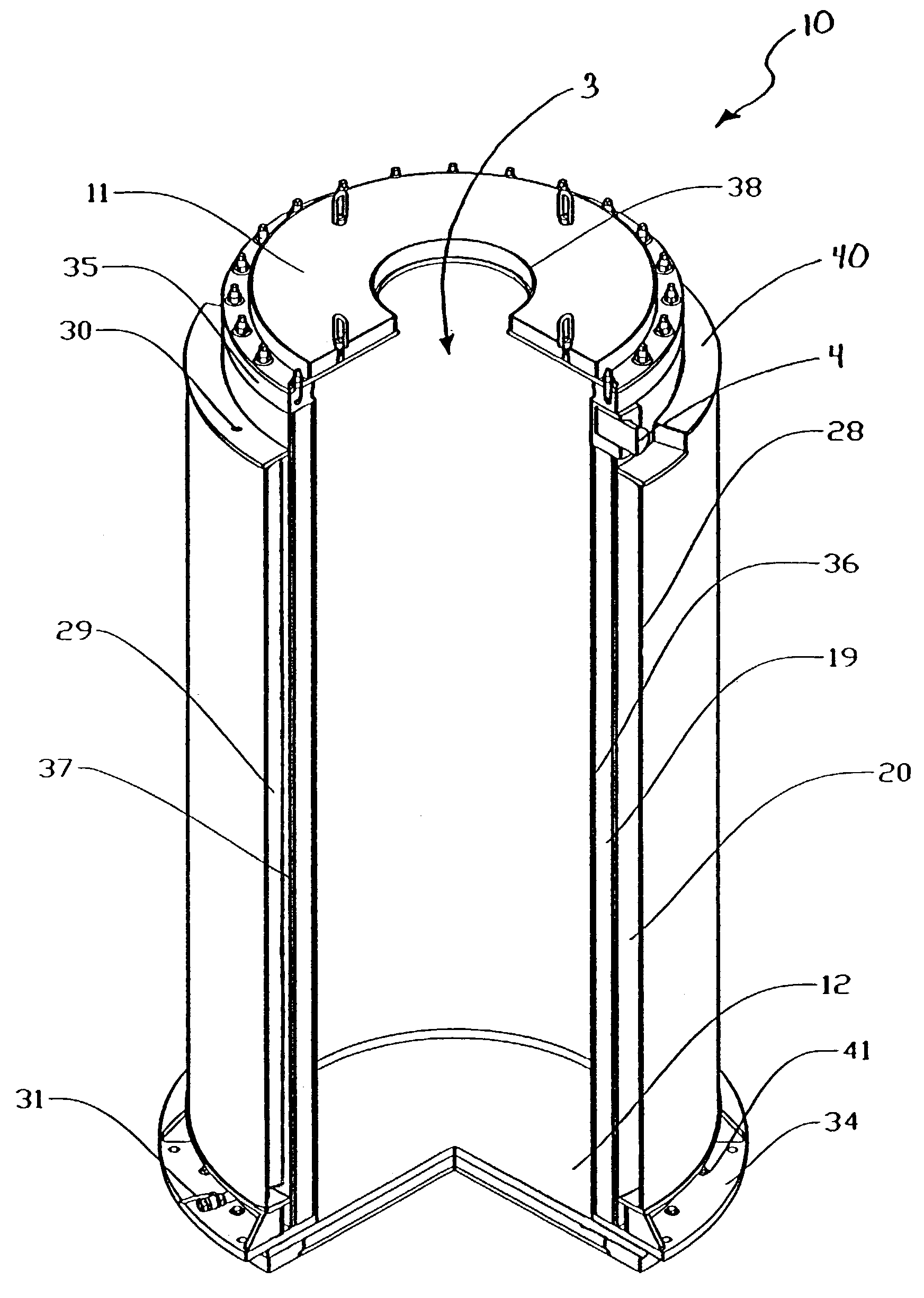
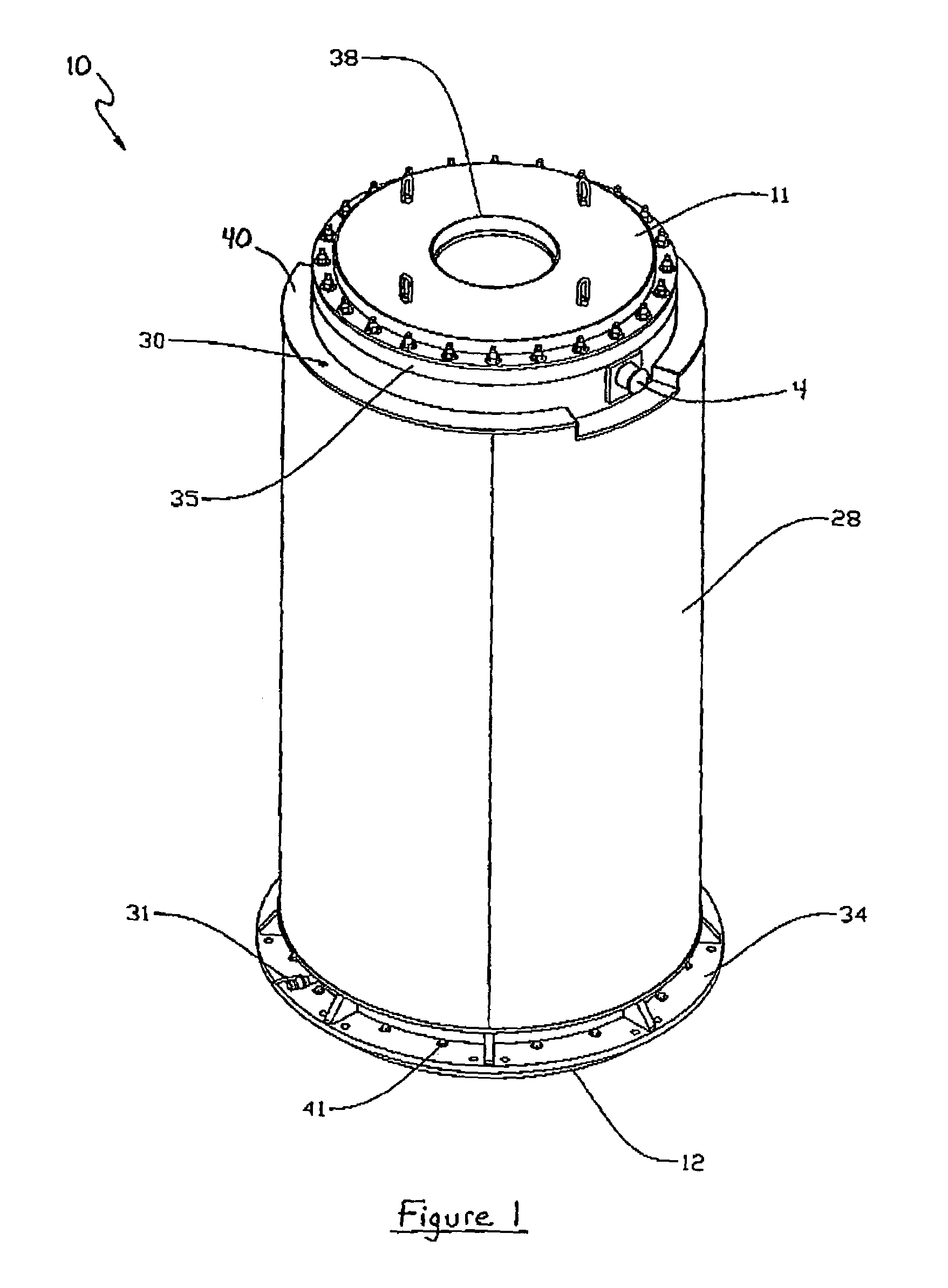
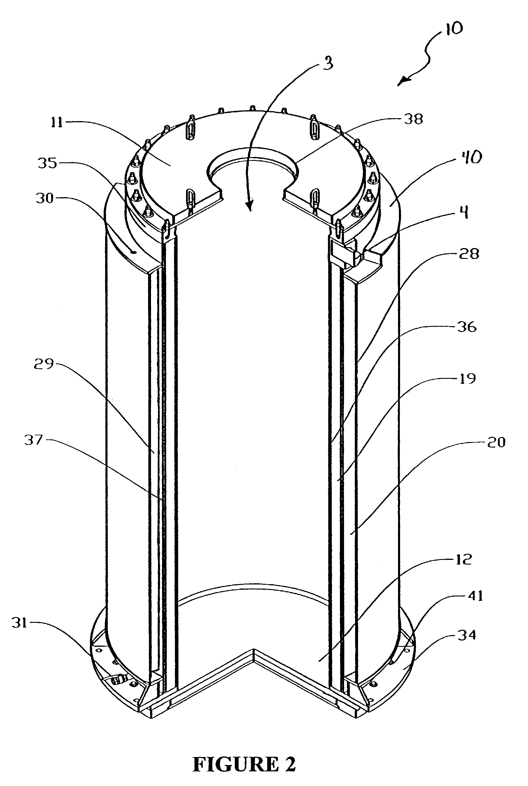
[0033]FIG. 1 illustrates an embodiment of the apparatus of the present invention, wherein cylindrical transfer cask 10 having a drainable jacket defined by jacket shell 28. A cask lid 11 is removable during the loading step. Cask lid 11 has lid opening 38 for facilitating access to cavity 3 (FIG. 2). Bottom lid 12 is secured to bottom flange 34 by a plurality of bolts 41 that extend through holes in bottom flange 34 and threadily engage bottom lid 12. Handles 4 are provided for attaching the crane.

[0034]Transfer cask 10 and jacket shell 28 have a top and bottom. As used herein throughout, “top” refers to the ends of jacket shell 28 and cask 10 that are closest in proximity to top flange 35, while “bottom” refers to the ends of jacket shell 28 and cask 10 that are closest in proximity to bottom flange 34.

[0035]Referring to FIG. 2, transfer cask 10 comprises cylindrical inner shell 36. Along with bottom lid 12, cylindrical inner shell 36 forms cavity 3 within which a canister of spent...


PUM


Abstract

A transfer cask for maximizing the radiation shielding for spent nuclear fuel during cask transfer procedures has a cylindrical inner shell forming a cavity within which a spent nuclear fuel canister can be placed; a cylindrical outer shell concentric with and surrounding the inner shell to form an annulus with the inner shell, the annulus adapted for receiving gamma absorbing material; a jacket shell concentric with and surrounding the second shell to form a jacket for holding a neutron absorbing liquid; the jacket shell having filling and drainage systems; and a removable bottom lid so that a canister can be lowered from the cavity into a transport cask or permanent storage cask.

Description

CROSS-REFERENCE TO RELATED APPLICATION[0001]This application is a divisional application of Ser. No. 10 / 101,028 filed Mar. 18, 2002 now U.S. Pat. No. 6,587,536. All applications are hereby incorporated by reference in their entireties.BACKGROUND OF THE INVENTION[0002]This invention relates to the field of transporting spent nuclear fuel and specifically to maximizing radiation shielding during spent nuclear fuel transfer procedures.[0003]In the operation of nuclear reactors, it is customary to remove fuel assemblies after their energy has been depleted down to a predetermined level. In the commercial nuclear industry, fuel assemblies are typically an assemblage of long, hollow, zircaloy tubes filled with enriched uranium. Upon depletion and subsequent removal, spent nuclear fuel is still highly radioactive and produces considerable heat, requiring that great care be taken in its packaging, transporting, and storing. Specifically, spent nuclear fuel emits extremely dangerous neutrons...

Claims


Application Information

Patent Timeline
Patent Type & Authority Patents(United States)
IPC IPC(8): G21C19/00G21C19/32G21F3/00G21F5/008G21F5/10G21F5/14G21F9/36
CPCG21C19/00G21C19/32G21F5/14Y02E30/30
Inventor SINGH, KRISHNA P.AGACE, STEPHEN J.
Owner HOLTEC INT
Why Eureka
Try Eureka