Tuning circuit with amplitude attenuation function and integrated circuit for radio communication apparatus

a technology of amplitude attenuation and integrated circuit, which is applied in the direction of anti-theft devices, instruments, and discrete pretuned circuits, which can solve the problem of large power consumption (about 1 a in terms of electrical current), and achieve the effect of eliminating the dependency of on-resistan

Inactive Publication Date: 2008-02-12
SEMICON COMPONENTS IND LLC +1
View PDF14 Cites 10 Cited by
  • Summary
  • Abstract
  • Description
  • Claims
  • Application Information

AI Technical Summary

Benefits of technology

[0011]Another aspect of the present invention is a tuning circuit having a coil and a capacitor, comprising: a switching element connected in parallel with the coil and the capacitor, the switching element changing a resistance of the tuning circuit when resonant, wherein changing the resistance by the switching element changes the amplitude of an output signal of the tuning circuit, the tuning circuit further comprising: a circuit to render an ON-resistance constant that eliminates dependency of the ON-resistance of the switching element on a power supply voltage, which is a source of a switching voltage for the switching element, and on temperature, wherein the circuit to render an ON-resistance constant supplies the switching element with the switching voltage to eliminate the dependency on the power supply voltage and on the temperature.

Problems solved by technology

When realizing the AGC function such as automatic control to reduce the amplitude of the AC signal when it is large, using an analog control system comprising the variable gain amplifier and the rectifier mentioned above renders power consumption large (about 1 μA in terms of electrical current).

Method used


Image

  • Tuning circuit with amplitude attenuation function and integrated circuit for radio communication apparatus
  • Tuning circuit with amplitude attenuation function and integrated circuit for radio communication apparatus
  • Tuning circuit with amplitude attenuation function and integrated circuit for radio communication apparatus

Examples


example 1

[0088]The basic circuits described as fundamental designs with reference to FIGS. 2 to 7 have the following characteristic items that need improvement.

[0089]That is, in the basic circuit shown in FIG. 5, a transistor (switching element) MN0 constituted by an n-type channel MOSFET varies in ON resistance (resistance when ON) in response to the variation of the gate voltage when ON and temperature. That is, transistor MN0 cannot accurately change the resistance R0 at the time of resonance of the tuning circuit due to the variation of the gate voltage and temperature.

[0090]Specifically, as shown in the characteristic graph of resistance R0 against temperature of FIG. 8A, in the case of the basic circuit indicated by an alternate long and short dashed line, resistance R0 increases and is not constant as temperature rises in the range of −50° C. to 100° C. Furthermore, as shown in the characteristic graph of resistance R0 against power supply voltage VDD applied to the gate of the transi...

example 2

[0100]Outline

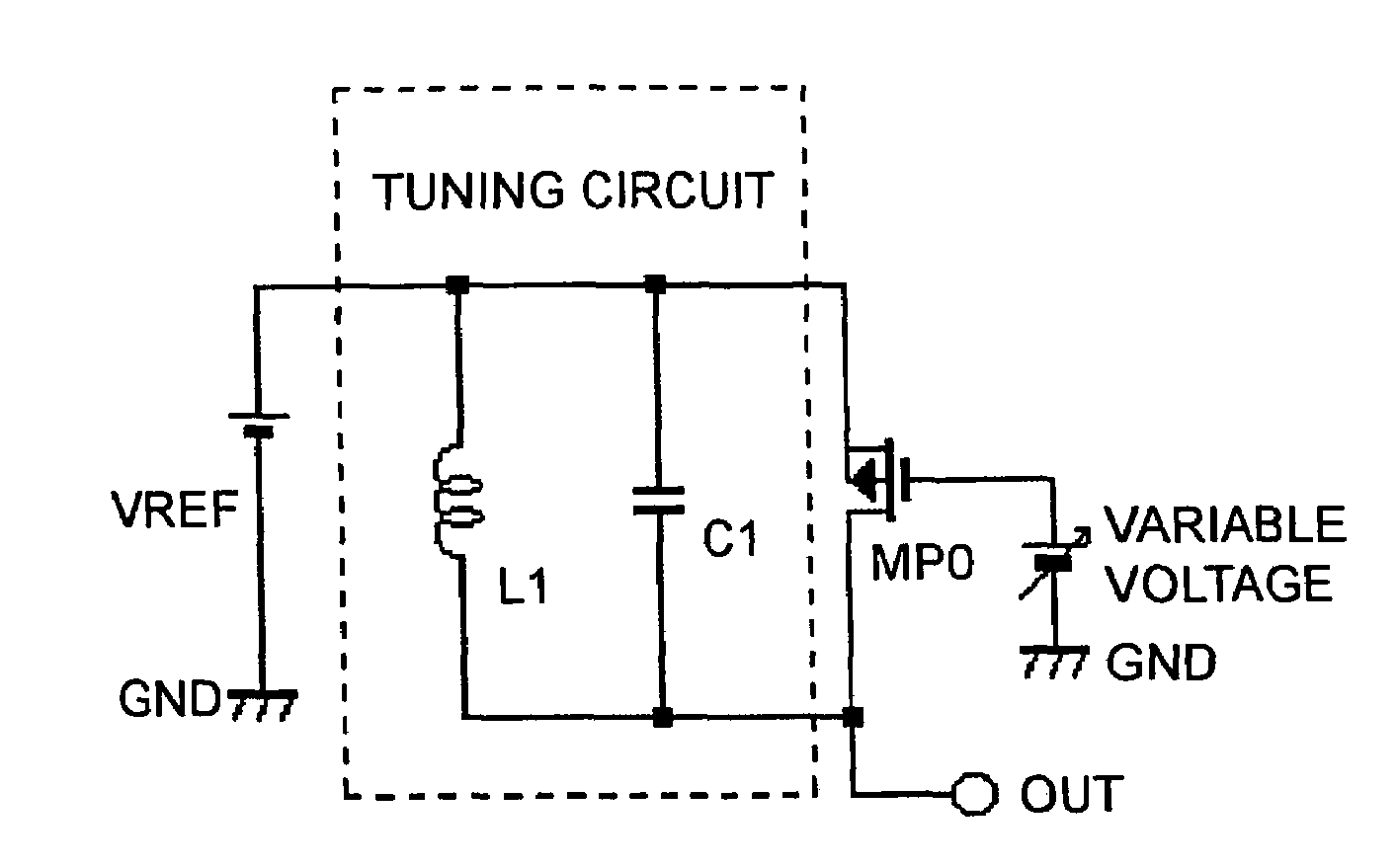
[0101]Another aspect of the invention intended for the above to-be-improved items as mentioned in the Example 1 will be described with reference to the circuit diagram of FIG. 11. Note that the present circuit is based on the basic circuit of FIG. 6 and thus a description is made below centered on differences from that in FIG. 6. A switching element as a resistance-adjustment element for changing the resistance of a tuning circuit when resonant is connected in parallel with the coil L1 and the capacitor C1. This switching element is constituted by a transistor MN0 that is an n-type channel MOSFET. By changing the resistance R0 of transistor MN0, the output signal amplitude of the tuning circuit is changed. The output signal from the inverted output terminal QN of D flip-flop FD2 is used as digital drive signal VAGC.

[0102]And a circuit to render the ON-resistance constant is provided for eliminating the dependency of transistor MN0's ON-resistance on power supply voltage...


PUM


Abstract

There is disclosed a tuning circuit having a coil and a capacitor comprises a resistance-adjustment circuit connected in parallel with the coil and the capacitor. The resistance-adjustment circuit changes a resistance of the tuning circuit when resonant. The resistance-adjustment circuit comprises a series circuit of a resistor and a switching element having an ON-resistance smaller than the resistance of the resistor, and turning on / off the switching element causes the resistance of the tuning circuit when resonant to change.

Description

NOTICE OF COPYRIGHTS AND TRADE DRESS[0001]A portion of the disclosure of this patent document contains material which is subject to copyright protection. This patent document may show and / or describe matter which is or may become trade dress of the owner. The copyright and trade dress owner has no objection to the facsimile reproduction by any one of the patent disclosure as it appears in the Patent and Trademark Office patent files or records, but otherwise reserves all copyright and trade dress rights whatsoever.RELATED APPLICATION INFORMATION[0002]The present application claims priority upon Japanese Patent Application No. 2003-402049 filed on Dec. 1, 2003, which is herein incorporated by reference.BACKGROUND OF THE INVENTION[0003]1. Field Of The Invention[0004]The present invention relates to a tuning circuit with an amplitude attenuation function and an integrated circuit for radio communication apparatuses.[0005]2. Description of the Related Art[0006]FIG. 16 shows a typical ex...

Claims


Application Information

Patent Timeline
Patent Type & Authority Patents(United States)
IPC IPC(8): H04B1/18G06K19/07H03G3/20H03G3/30H03J3/18H03J3/20H03J5/24
CPCB60R25/24H03J5/246G06K19/0723Y02B60/50H03J3/20H03J3/18
Inventor UMEWAKA, MASAHIROYAMAMOTO, HIROYASEKINE, KEITAROUHYOUGO, AKIRAMORIJIRI, KEIJI
Owner SEMICON COMPONENTS IND LLC
Why Eureka
Try Eureka