Drying fan

a fan and fan body technology, applied in the direction of wind motors with parallel air flow, wind motors with perpendicular air flow, liquid fuel engine components, etc., can solve the problems of affecting the use of the fan, the most difficult area to dry, and the longest drying time, so as to increase the supply air, maximize the radii, and facilitate the use.

Active Publication Date: 2008-02-19
THERMA STOR LLC
View PDF12 Cites 37 Cited by
  • Summary
  • Abstract
  • Description
  • Claims
  • Application Information

AI Technical Summary

Benefits of technology

[0007]In the preferred embodiment, the length of the duct upstream of the axial fan blades is minimized, to allow the blades to be supplied or “fed” with as much air as they can possibly move, and to avoid starving the blades for supply air. An intake cowling is provided and enhances this supply air.
[0008]In further embodiments, the axial fan blades are moved as close as possible to the wall and/or floor. This is desirable so that intake air does not have to change direction and accelerate before becoming exhaust air, or only has to undergo minimal directional change. The air moving through the fan stays close to the wall and/or floor in order to dry the wall and/or floor, particularly at the corner. Keeping the blades close to the wall and to the floor also eliminates the need for large radiused round cowling sections at the wall and/or the floor because the wall and floor upstream of the intake acts as a section of intake “duct”. This “duct” helps the air to establish an axial direction of flow, and hence aids in supplying the blades with intake air. This intake air also aids in structure drying. In further embodiments, the remaining cowling sides opposite the wall and the floor may have maximized radii in order to aid air supply, with the limiting factor being exterior housing dimensions. In preferred embodiments, all exterior housing surfaces are shaped for portability and storable stackability.
[0009]Further desirable aspects include stator vanes removing downstream rotation from the air and transferring same into useful axial air velocity. I

Problems solved by technology

The corner between a wall and a floor is the most difficult area to dry and takes the longest time to dry.
Without static pressure, if one attempts to expand the air too

Method used


Image

  • Drying fan
  • Drying fan
  • Drying fan

Examples


Embodiment Construction

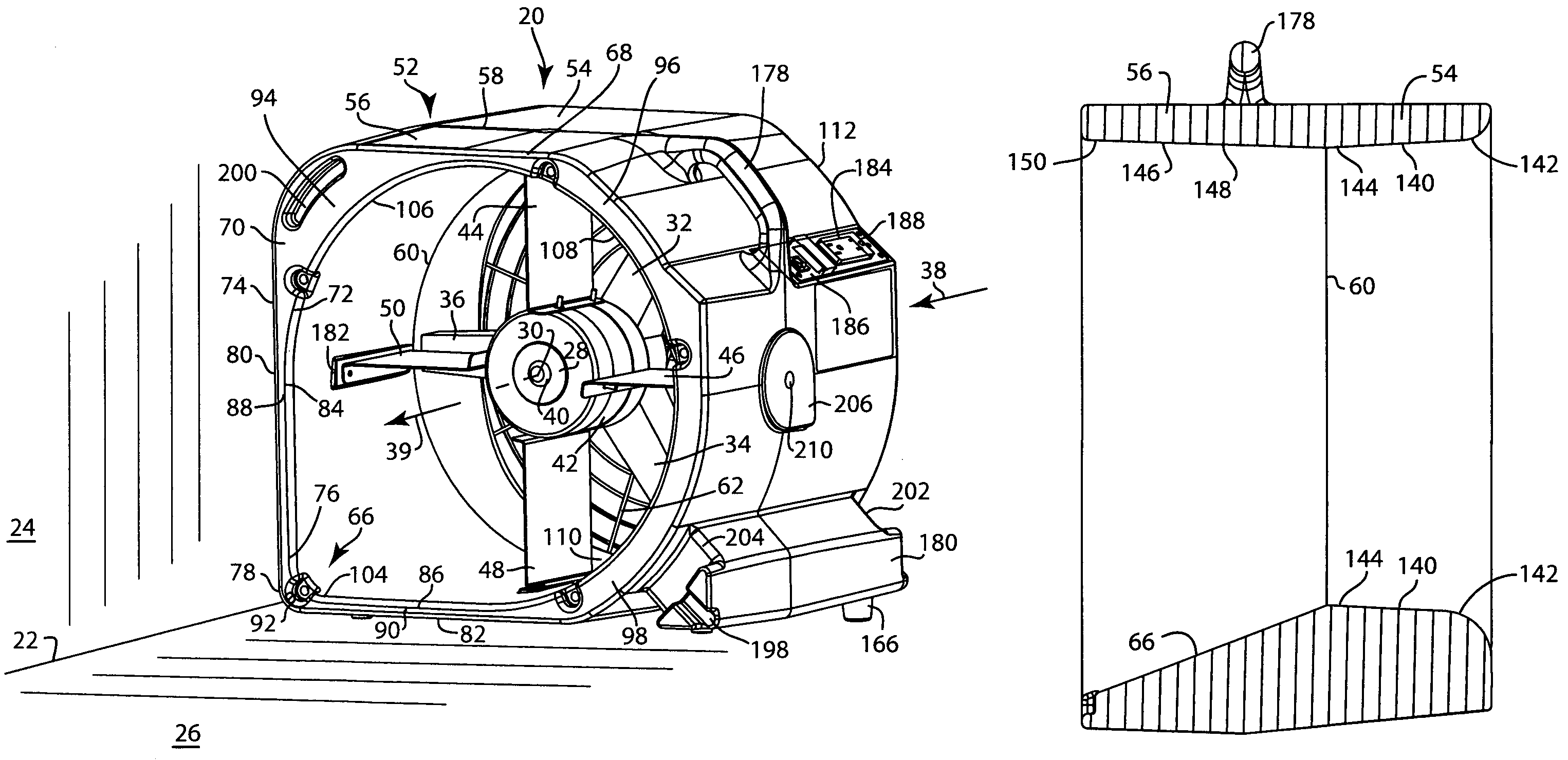
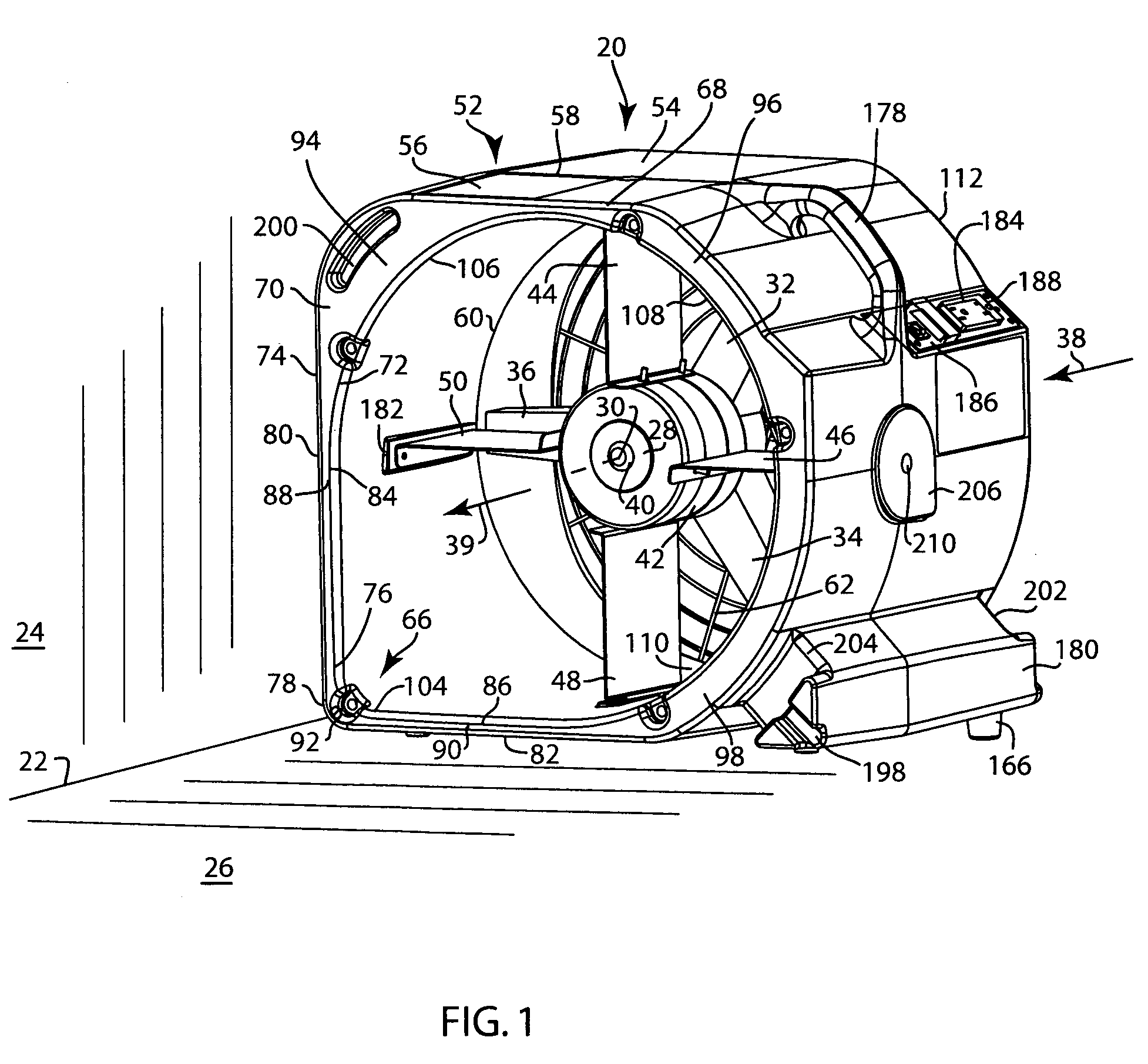
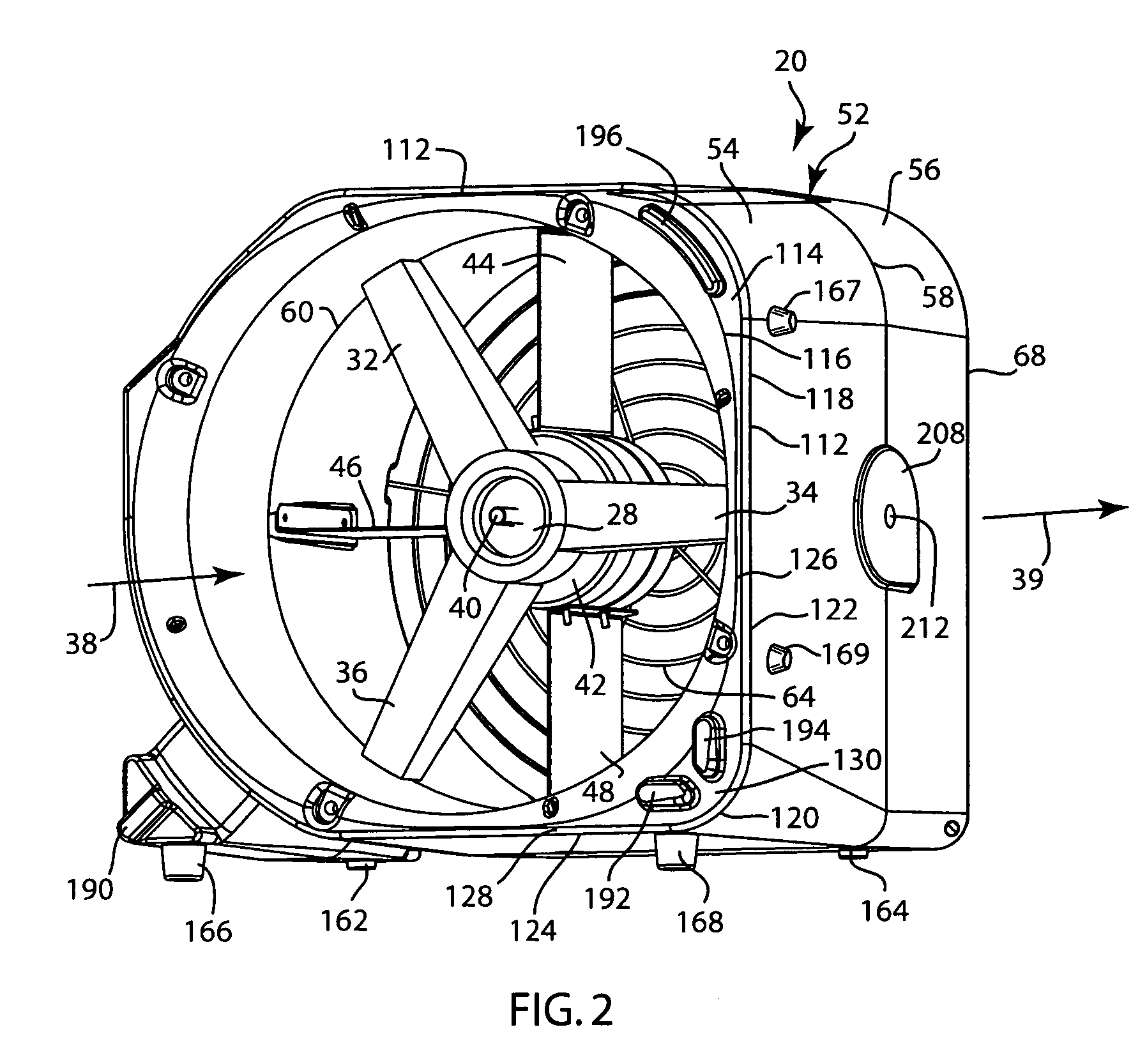
[0023]FIGS. 1-4 show a drying fan 20 for water damage restoration, particularly for drying a room corner 22 extending axially along an interface between a wall 24 and a floor 26. A fan hub 28 is rotational about rotation axis 30 generally parallel to the noted axial extension of room corner 22, namely preferably within a cone at a compound angle less than or equal to about 10° tapered downwardly toward floor 26 and less than or equal to about 10° tapered inwardly toward wall 24. Hub 28 has a plurality of fan blades 32, 34, 36 extending radially therefrom for moving air along an axial flow direction from upstream to downstream as shown at arrows 38, 39, upon rotation of hub 28. Hub 28 is mounted on a motor shaft 40 of electrical motor 42 mounted by stator vanes 44, 46, 48, 50 in a shrouded housing 52 having an axial flow path therethrough as shown at arrows 38, 39 along axis 30.

[0024]Housing 52 is a plastic molded member, preferably polyethylene, preferably formed by rotational moldi...


PUM


Abstract

A drying fan, including for water damage restoration, including for drying a room corner extending axially along an interface between a wall and a floor, has a shrouded housing having an axial flow path therethrough, an intake cowling receiving intake air, and an exhaust cowling discharging exhaust air and having a tapered ramp both a) expanding the airflow and b) directing the airflow where desired.

Description

CROSS-REFERENCE TO RELATED APPLICATIONS[0001]This application claims the benefit of and priority from Provisional U.S. Patent Application No. 60 / 550,012, filed Mar. 4, 2004. Reference is also made to commonly owned co-pending U.S. patent application Ser. No. 11 / 068,341, filed on even date herewith, incorporated herein by reference.BACKGROUND AND SUMMARY[0002]The invention relates to drying fans, including for water damage restoration and other applications.[0003]In the water damage restoration industry, fans are used for drying a water damaged structure, including carpeting, furniture, framework, etc. If water can be evaporated quickly, damage can be minimized. The fans move air over the water damaged surfaces at high velocity. The two types of fans typically used are axial propeller type fans and centrifugal squirrel cage type fans. The present invention is directed to improvements in axial fans because of their lower electrical current requirements.[0004]The corner between a wall ...

Claims


Application Information

Patent Timeline
IPC IPC(8): F04D29/54
CPCF04D29/601F24F7/007
Inventor TEJEDA, MARCO A.
Owner THERMA STOR LLC
Why Eureka
Try Eureka