Chopper amplifier circuit apparatus operable at low voltage utilizing switched operational amplifier

a low-frequency amplifier and operational amplifier technology, applied in electronic switching, pulse technique, amplifiers with semiconductor devices/discharge tubes, etc., can solve the problems of difficult to apply the two techniques to the low-frequency amplifier by utilizing an analog switch, increase the low frequency (1/f) noise, and increase the noise floor of the baseband, so as to achieve simple circuit configuration, lower voltage, and high reliability

Inactive Publication Date: 2008-02-26
SEMICON TECH ACADEMIC RES CENT
View PDF22 Cites 32 Cited by
  • Summary
  • Abstract
  • Description
  • Claims
  • Application Information

AI Technical Summary

Benefits of technology

[0023]An essential object of the present invention is to provide a chopper amplifier circuit apparatus capable of solving the above-described problems, having a simpler circuit configuration, having a higher reliability, and being operable at a lower voltage as compared with those of the prior art.
[0031]Therefore, according to the chopper amplifier circuit apparatus according to the present invention, an output signal from the chopper demodulator device is chopper-modulated by the second chopper modulator device, and then is fed back to the input terminal of the amplifying device. Therefore, it is possible to provide a chopper amplifier circuit apparatus having a simpler circuit configuration, having a higher reliability, and being operable at a lower voltage as compared with those of the prior art. In addition, the chopper amplifier circuit apparatus is provided with a circuit for the auto-zero operation, and therefore, a DC offset can be appropriately performed on the input signal, and the low frequency noise can be reduced.

Problems solved by technology

However, in the scaled CMOS technique, increase in a direct-current (DC) offset voltage and increase in a low frequency (1 / f) noise lead to a serious problem.
The auto-zero operation technique thus makes it possible to reduce the low-frequency noises of the amplifier circuit, however, one problem of the auto-zero operation technique is to increase in a baseband noise floor caused by aliasing of a broadband noise unique to a sampling process.
The above-mentioned two techniques are required for a low noise amplifier operating at a low voltage, however, it is difficult to apply the two techniques to the low noise amplifier by utilizing an ordinary analog switch.
The reason for the difficulty is that the analog switch cannot transmit an intermediate voltage level by using a low power source voltage.
Under these conditions, there was such a problem that it was difficult to realize an electronic circuit utilizing the analog switch such as an A / D converter, a D / A converter or a DC amplifier circuit.
However, in the former case, such a device is required that has a withstand voltage higher than that of an ordinary device, and this causes problems complication of process, deterioration in reliability, and an increase in circuit area.
In addition, in the latter case, there are problems of an increase in a leakage current and deterioration in reliability.

Method used


Image

  • Chopper amplifier circuit apparatus operable at low voltage utilizing switched operational amplifier
  • Chopper amplifier circuit apparatus operable at low voltage utilizing switched operational amplifier
  • Chopper amplifier circuit apparatus operable at low voltage utilizing switched operational amplifier

Examples


first preferred embodiment

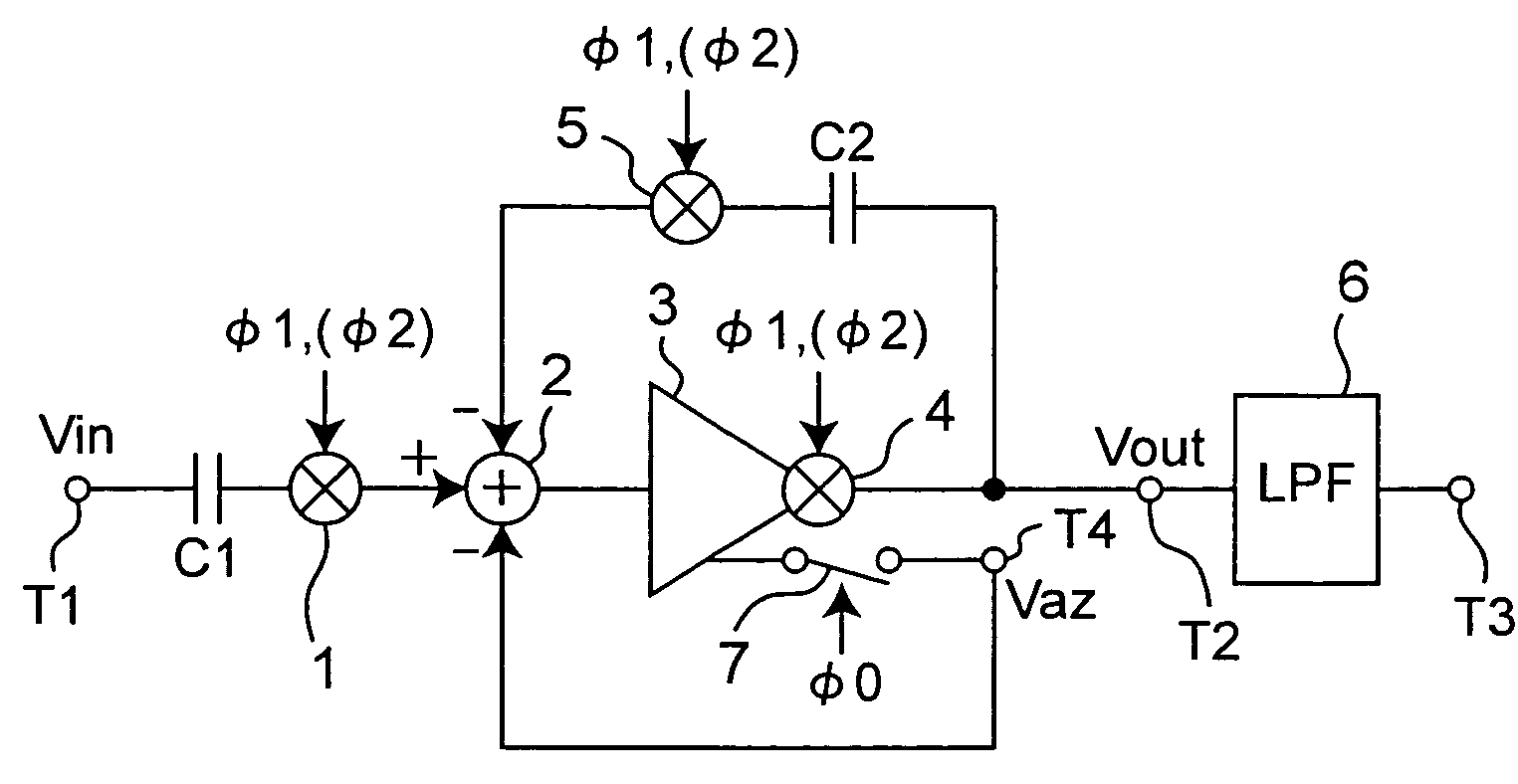
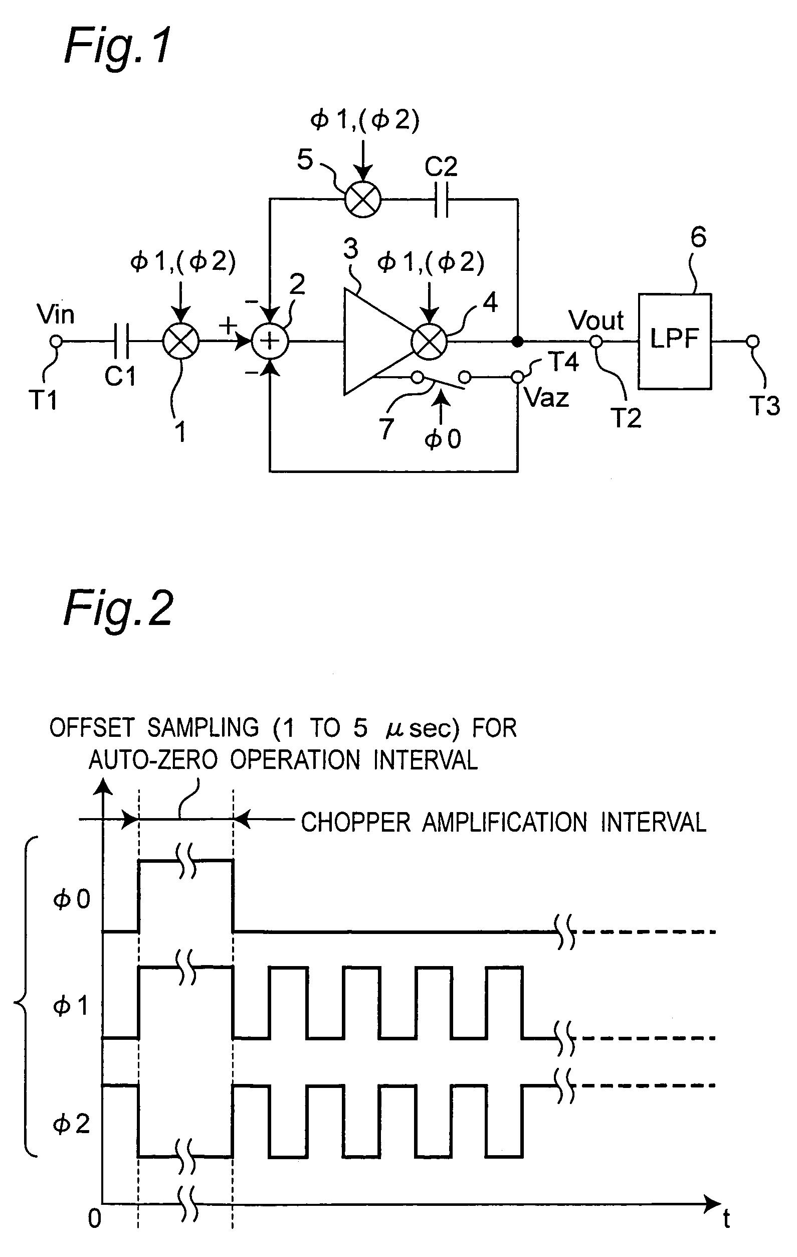
[0057]FIG. 1 is a block diagram showing a configuration of a chopper amplifier circuit according to the first preferred embodiment of the present invention. FIG. 2 is a timing chart showing control signals φ0, φ1, and φ2 for use in the chopper amplifier circuit of FIG. 1. The chopper amplifier circuit according to the first preferred embodiment is a low noise amplifier operating at a low power source voltage based on auto-zero operation and chopper stabilization. In a low voltage operation of the chopper stabilization, an input voltage level is unstable, and therefore, the chopper modulator 61 and the chopper demodulator 62 according to the prior art cannot be implemented in floating analog switches. In order to solve this problem, the chopper amplifier circuit according to the present preferred embodiment is characterized by including a switched operational amplifier 3 having a negative feedback as shown in FIG. 1.

[0058]Referring to FIG. 1, the chopper amplifier circuit according t...

second preferred embodiment

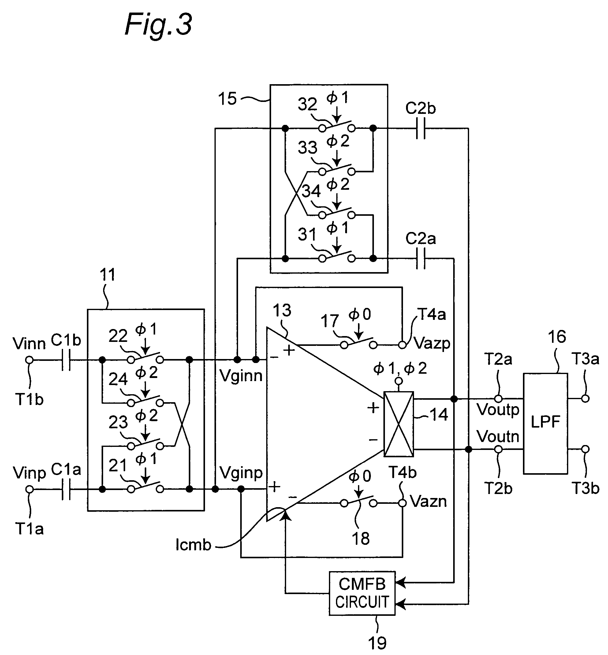
[0063]FIG. 3 is a block diagram showing a configuration of a chopper amplifier circuit according to the second preferred embodiment of the present invention. Referring to FIG. 3, the chopper amplifier circuit according to the second preferred embodiment is characterized by realizing the chopper amplifier circuit according to the first preferred embodiment using a fully-differential amplifier. The present chopper amplifier circuit is constituted by including a chopper modulator 11, a switched operational amplifier 13, a chopper modulator 15 for a negative feedback circuit, a low-pass filter 16, a common mode feedback circuit (referred to as a CMFB circuit hereinafter) 19, input terminals T1a and T1b, intermediate output terminals T2a and T2b, output terminals T3a and T3b, coupling capacitors C1a and C1b, capacitors C2a and C2b for the negative feedback circuit, switch circuits 17 and 18 for auto-zero operation, and terminals T4a and T4b. The switched operational amplifier 13 is a ful...


PUM


Abstract

In a chopper amplifier circuit operable at a low voltage utilizing a switched operational amplifier, a chopper modulator chopper-modulates an input signal according to a predetermined control signal, and outputs a chopper-modulated signal. An amplifier circuit constituted by the switched operational amplifier amplifies the chopper-modulated signal outputted from the chopper modulator, and outputs an amplified chopper-modulated signal. A chopper-demodulator of the switched operational amplifier chopper-demodulates the amplified chopper-modulated signal outputted from the amplifier circuit according to the control signal, and outputs a demodulated output signal as a chopper-amplified output signal from an output terminal. A chopper modulator chopper-modulates a demodulated signal outputted from the chopper demodulator according to the control signal, and outputs a chopper-modulated signal to an input terminal of the amplifier circuit.

Description

BACKGROUND OF THE INVENTION[0001]1. Field of the Invention[0002]The present invention relates to a chopper amplifier circuit apparatus which is formed by, for example, a CMOS circuit, is constituted by utilizing a switched operational amplifier and a chopper modulator, and is operable at a low voltage.[0003]2. Description of the Related Art[0004]Recently, a sensor chip employing a mixed signal CMOS technique has been applied to detection and monitoring of a biological function (See first and second non-patent documents described below, for example). A low noise amplifier is one of the most important circuits in the sensor chip, since the sensor chip detects a low-level signal. However, in the scaled CMOS technique, increase in a direct-current (DC) offset voltage and increase in a low frequency (1 / f) noise lead to a serious problem.[0005]Auto-zero operation and chopper stabilization are techniques widely used to reduce these noises (See a third non-patent document described below, f...

Claims


Application Information

Patent Timeline
Patent Type & Authority Patents(United States)
IPC IPC(8): H03F1/02
CPCH03F3/393H03F3/45775
Inventor YOSHIDA, TAKESHIIWATA, ATSUSHISASAKI, MAMORUMASHIMO, TAKAYUKIMASUI, YOSHIHIRONAKATSUKA, JUNJI
Owner SEMICON TECH ACADEMIC RES CENT
Why Eureka
Try Eureka