
Laser remote sensing of backscattered light from a target sample

a target sample and laser remote sensing technology, applied in the field of laser remote sensing, can solve the problems of inconvenient sample preparation, and unable to detect backscattered light in a direction that is not directional, and the technique requires little or no sample preparation

Active Publication Date: 2008-02-26
NAT TECH & ENG SOLUTIONS OF SANDIA LLC
View PDF10 Cites 20 Cited by
  • Summary
  • Abstract
  • Description
  • Claims
  • Application Information

AI Technical Summary

Benefits of technology

[0012]The back surface can further comprise a substrate that absorbs the target sample from an environment. The substrate can be a SERS or SEF substrate. The laser is preferably

Problems solved by technology

In addition, the technique requires little or no sample preparation, is nondestructive, and can use water as a solvent (since water is a poor Raman scatterer).
Unfortunately, Raman scattering is an inherently weak process, precluding the possibility of remote trace analysis without some form of enhancement.
However, in the usual LIDAR system, the backscattered light is nondirectional and the returned signal falls off by an inverse-square dependence with range.

Method used


Image

  • Laser remote sensing of backscattered light from a target sample
  • Laser remote sensing of backscattered light from a target sample
  • Laser remote sensing of backscattered light from a target sample

Examples


Embodiment Construction

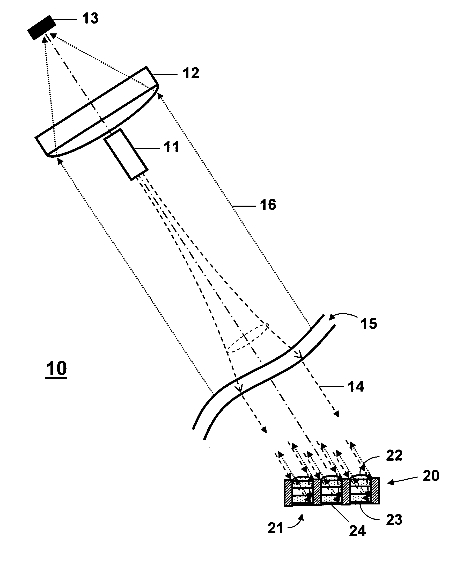
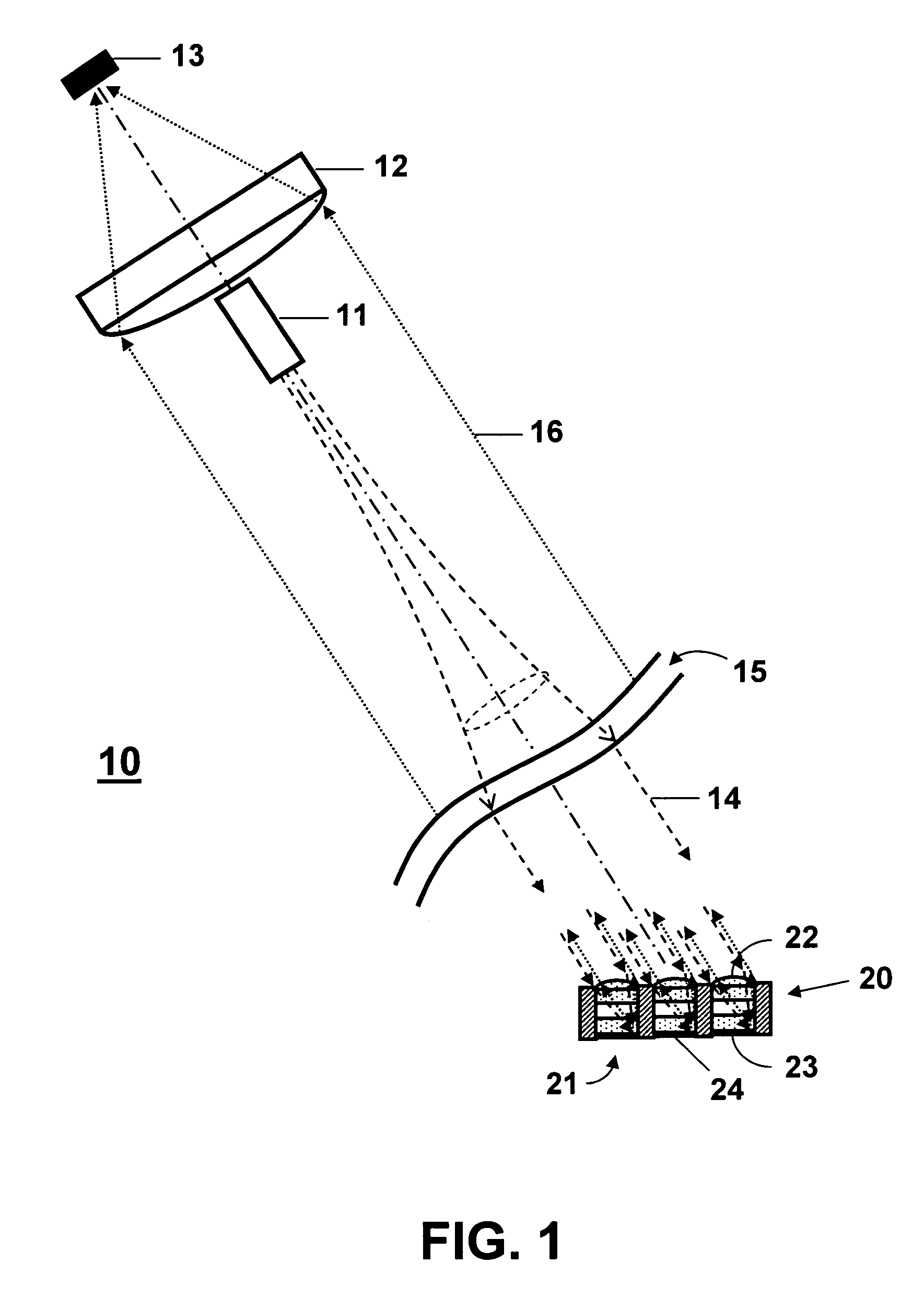
[0020]In FIG. 1 is shown a schematic illustration of a laser remote sensing apparatus 10, comprising a laser source 11, a sensing optic 20, a collection telescope 12, and a spectrally-resolved detector 13. The apparatus 10 can be used to obtain SERS or fluorescence measurements of molecules that are on or within a depth of focus of the back surface 23 of the distant sensing optic 20.

[0021]For SERS measurements, the laser 11 can provide a monochromatic light source that has high power and frequency, and is not absorbed in the propagating atmosphere. Preferably the laser light has a narrow bandwidth and propagates with low divergence. For example, the laser 11 can be a high-power visible or near-infrared laser. For laser-induced fluorescence, the laser can be a monochromatic laser at a known excitation wavelength of a sample molecule. Alternatively, the laser can be a tunable laser that can be tuned over a broad frequency range, to enable excitation of a sample comprising unknown spec...


PUM


Abstract

A laser remote sensing apparatus comprises a laser to provide collimated excitation light at a wavelength; a sensing optic, comprising at least one optical element having a front receiving surface to focus the received excitation light onto a back surface comprising a target sample and wherein the target sample emits a return light signal that is recollimated by the front receiving surface; a telescope for collecting the recollimated return light signal from the sensing optic; and a detector for detecting and spectrally resolving the return light signal. The back surface further can comprise a substrate that absorbs the target sample from an environment. For example the substrate can be a SERS substrate comprising a roughened metal surface. The return light signal can be a surface-enhanced Raman signal or laser-induced fluorescence signal. For fluorescence applications, the return signal can be enhanced by about 105, solely due to recollimation of the fluorescence return signal. For SERS applications, the return signal can be enhanced by 109 or more, due both to recollimation and to structuring of the SERS substrate so that the incident laser and Raman scattered fields are in resonance with the surface plasmons of the SERS substrate.

Description

STATEMENT OF GOVERNMENT INTEREST[0001]This invention was made with Government support under contract no. DE-AC04-94AL85000 awarded by the U.S. Department of Energy to Sandia Corporation. The Government has certain rights in the invention.FIELD OF THE INVENTION[0002]The present invention relates to laser remote sensing and, in particular, to laser remote sensing based on backscattered Raman or fluorescence light from a target sample.BACKGROUND OF THE INVENTION[0003]Significant investment has been made in developing optical methods for the remote or stand-off detection of trace chemicals, environmental pollutants, high explosives, and chemical and biological agents. In particular, detection can be achieved by laser remote sensing based on Raman scattering or laser-induced fluorescence from a target sample. Therefore, radiation detected at wavelengths different from that of the laser's output can contain highly specific molecular information that can be used to determine the compositio...

Claims


Application Information

Patent Timeline
IPC IPC(8): G01J3/44G01J3/443G01N21/17G01N21/35G01N21/39G01N21/64G01N21/65
CPCG01J3/02G01J3/0208G01J3/44G01N21/6402G01N21/658G01N2021/1793G01N2021/392
Inventor SWEATT, WILLIAM C.WILLIAMS, JOHN D.
Owner NAT TECH & ENG SOLUTIONS OF SANDIA LLC
Learn More