Apparatus for and method of controlling temperature of exhaust gas sensor, and recording medium storing program for controlling temperature of exhaust gas sensor

a technology of exhaust gas sensor and recording medium, which is applied in the direction of electrical control, process and machine control, instruments, etc., can solve the problems of difficult to keep the temperature of the active element in the desired temperature range stably and reliably, and achieve the effect of increasing the amount of heat generated by the catalyst and increasing the accuracy of the estimated mated valu

Inactive Publication Date: 2008-03-04
HONDA MOTOR CO LTD
View PDF12 Cites 18 Cited by
  • Summary
  • Abstract
  • Description
  • Claims
  • Application Information

AI Technical Summary

Benefits of technology

[0094]In the above thermal model, a temperature change component depending on the speed of the exhaust gas refers to a temperature change component of the catalyst (a passage-defining member) based on heating of the catalyst due to its own exhaust gas purifying action. Specifically, as the speed of the exhaust gas increases, the amount of the exhaust gas with which the catalyst reacts per given time increases, resulting in an increase in the amount of heat generated by the catalyst. Accordingly, the temperature change component of the catalyst based on its heating depends on the speed of the exhaust gas. Based on the thermal model, it is possible to estimate accurately a change per given time in the temperature of the passage-defining member which d

Problems solved by technology

Consequently, when the operating state of an internal combustion engine changes frequently and hence the temperature of the exhaust gas emitted therefrom changes frequently, it is difficult to keep the temperature of the activ

Method used


Image

  • Apparatus for and method of controlling temperature of exhaust gas sensor, and recording medium storing program for controlling temperature of exhaust gas sensor
  • Apparatus for and method of controlling temperature of exhaust gas sensor, and recording medium storing program for controlling temperature of exhaust gas sensor
  • Apparatus for and method of controlling temperature of exhaust gas sensor, and recording medium storing program for controlling temperature of exhaust gas sensor

Examples


second embodiment

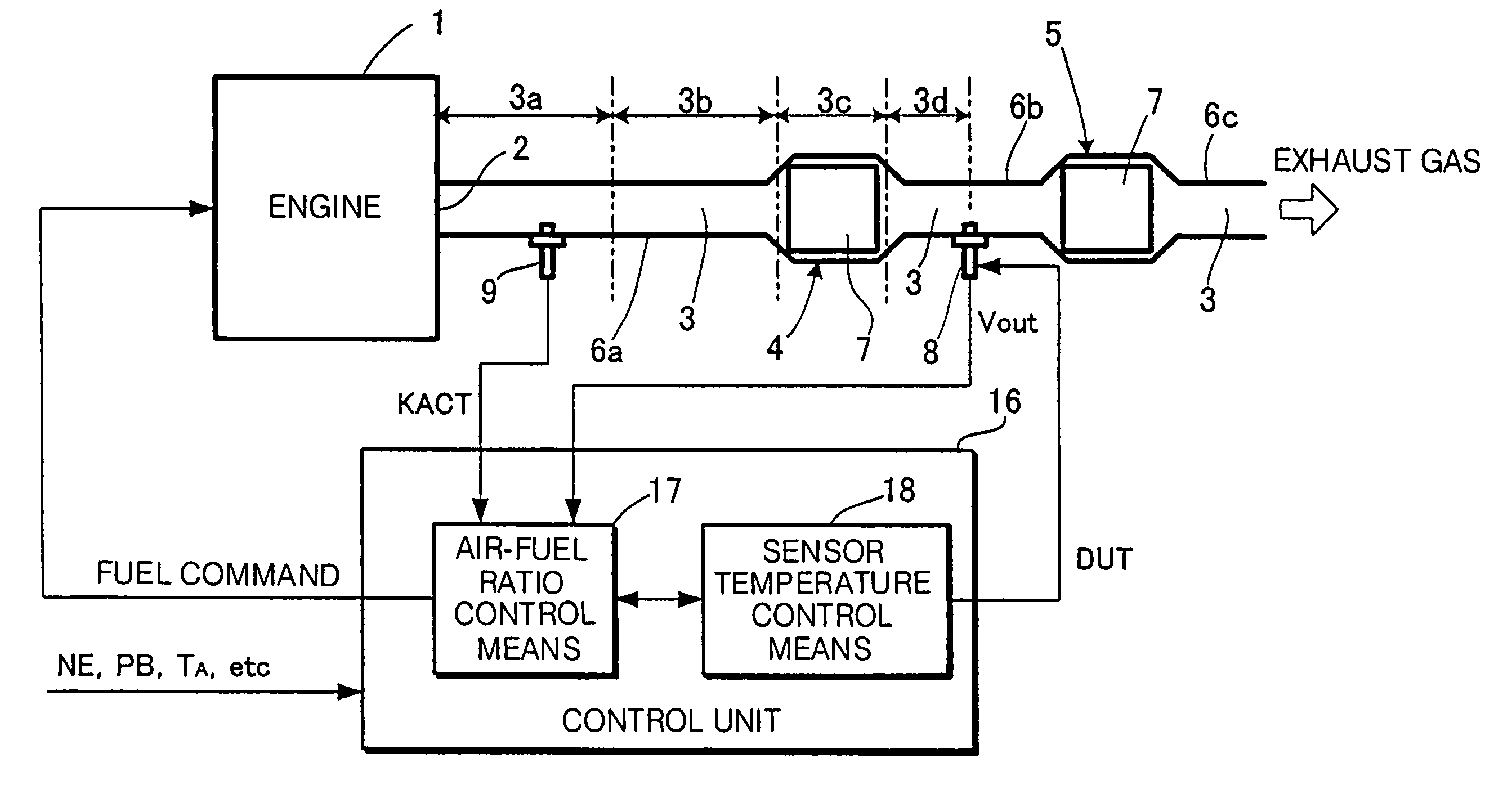
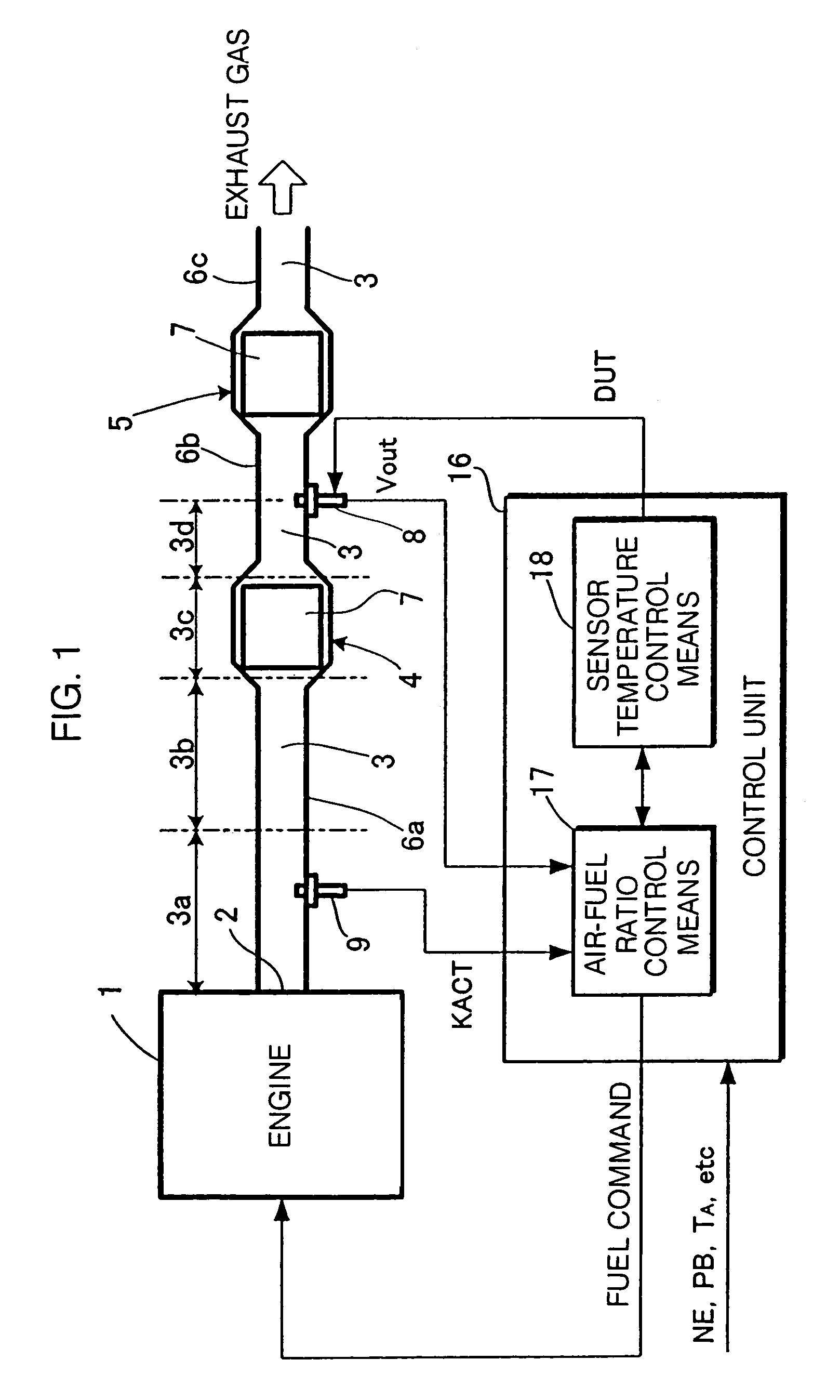
[0268]In the second embodiment, as shown in FIG. 12, an exhaust gas temperature sensor 29 for detecting an exhaust gas temperature Tx is mounted on an intermediate portion of the exhaust pipe 6a of the exhaust passage 3. A detected value of the exhaust gas temperature Tx is supplied from the exhaust gas temperature sensor 29 to the sensor temperature control means 18 (specifically, the exhaust temperature observer 19) of the control unit 16 for estimating the exhaust gas temperature Tgd in the vicinity of the location of the O2 sensor 8. The exhaust gas temperature sensor 29 is not required to be dedicated for the process of controlling the element temperature TO2 of the O2 sensor 8, but may be an existing temperature sensor provided for performing another purpose than the controlling of the element temperature TO2, i.e., for performing a process of controlling the exhaust gas temperature to protect the catalyst against enrichment of the air-fuel ratio.

[0269]In the second embodiment...

fourth embodiment

[0274]If the exhaust gas temperature sensor 29 is located for detecting the exhaust gas temperature Tx in the vicinity of the inlet of the catalytic converter 4 as shown in FIG. 14(b), then the exhaust port thermal model 24 and the pre-CAT exhaust system thermal models 25, 26 are dispensed with, and the detected value Tx (latest value) of the exhaust gas temperature from the exhaust gas temperature sensor 29 is supplied as the value of “Tgb” for use in the calculation of the equation (8-1) to the in-CAT exhaust system thermal model 27. This arrangement allows the exhaust gas temperature Tgd to be estimated in the vicinity of the location of the O2 sensor 8.

fifth embodiment

[0275]If the exhaust gas temperature sensor 29 is located for detecting the exhaust gas temperature Tx in the vicinity of the outlet of the catalytic converter 4 as shown in FIG. 14(c), then the exhaust port thermal model 24, the pre-CAT exhaust system thermal models 25, 26, and the in-CAT exhaust system thermal model 27 are dispensed with, and the detected value Tx (latest value) of the exhaust gas temperature from the exhaust gas temperature sensor 29 is supplied as the value of “Tgb” for use in the calculation of the equation (9-1) to the in-CAT exhaust system thermal model 27. This arrangement allows the exhaust gas temperature Tgd to be estimated in the vicinity of the location of the O2 sensor 8.

[0276]In any of the third through fifth embodiments, the other details of the processing sequence of the sensor temperature control means 18 than the process of estimating the exhaust gas temperature Tgd may be identical to those of the first embodiment.

[0277]Although not described in...


PUM


Abstract

The temperature of an exhaust gas flowing through an exhaust passage 3 is estimated or detected, and the temperature of an active element of an exhaust gas sensor 8. (O2 sensor) is controlled at a predetermined target temperature by a heater using the estimated or detected temperature of the exhaust gas. For estimating the temperature of the exhaust gas in the vicinity of the exhaust gas sensor 8, the exhaust passage 3 extending up to the exhaust gas sensor 8 is divided into a plurality of partial exhaust passageways 3a through 3d, the temperatures of the exhaust gas in the partial exhaust passageways 3a through 3d are estimated successively from an exhaust port 2 of an engine 1. The temperature of the exhaust gas is estimated according to an algorithm which takes into account a heat transfer between the exhaust gas and passage-defining members 6a, 6b, 7 which define the exhaust passage 3 and a heat radiation from the passage-defining members into the atmosphere. A control input that is applied to the heater includes at least a component depending on the temperature of the active element of the exhaust gas sensor 8 and a component depending on the temperature of the exhaust gas. Even if the temperature of the exhaust gas changes, the temperature of the active element of the exhaust gas sensor 8 can be controlled stably at the desired temperature.

Description

[0001]This is a Division of application Ser. No. 10 / 401,892 filed Mar. 31, 2003 now U.S. Pat. No. 6,823,839. The disclosure of the prior application(s) is hereby incorporated by reference herein in its entirety.BACKGROUND OF THE INVENTION[0002]1. Field of the Invention[0003]The present invention relates to an apparatus for and a method of controlling the temperature of an exhaust gas sensor disposed in the exhaust passage of an internal combustion engine, and a recording medium storing a program for controlling the temperature of such an exhaust gas sensor.[0004]2. Description of the Related Art[0005]Exhaust gas sensors are often disposed in the exhaust passages of internal combustion engines for detecting a physical quantity as to an exhaust gas component state, such as an exhaust gas component concentration, for the purpose of controlling the operation of the internal combustion engine or monitoring the status of an exhaust gas purifying system. Specifically, an exhaust gas sensor...

Claims


Application Information

Patent Timeline
IPC IPC(8): F02D41/00B60T7/12G01N27/409F02D41/14F02D45/00G01N27/406G05D23/19G05D23/24G05D23/27
CPCG05D23/2401G05D23/2716G05D23/1919G05D23/27
Inventor YASUI, YUJIIWAKI, YOSHIHISA
Owner HONDA MOTOR CO LTD
Why Eureka
Try Eureka