
Alignment device for fabricating optical disk

a technology of alignment device and optical disc, which is applied in the direction of auxillary welding device, soldering apparatus, instruments, etc., can solve the problems of time required, inability to achieve recording and reproduction at a high density, and inability to meet the joining force of the cover sheet and the disc substrate, so as to achieve satisfactory high dimensional accuracy, eliminate the generation of play, and accurately position

Inactive Publication Date: 2008-03-04
FUJIFILM HLDG CORP +1
View PDF8 Cites 4 Cited by
  • Summary
  • Abstract
  • Description
  • Claims
  • Application Information

AI Technical Summary

Benefits of technology

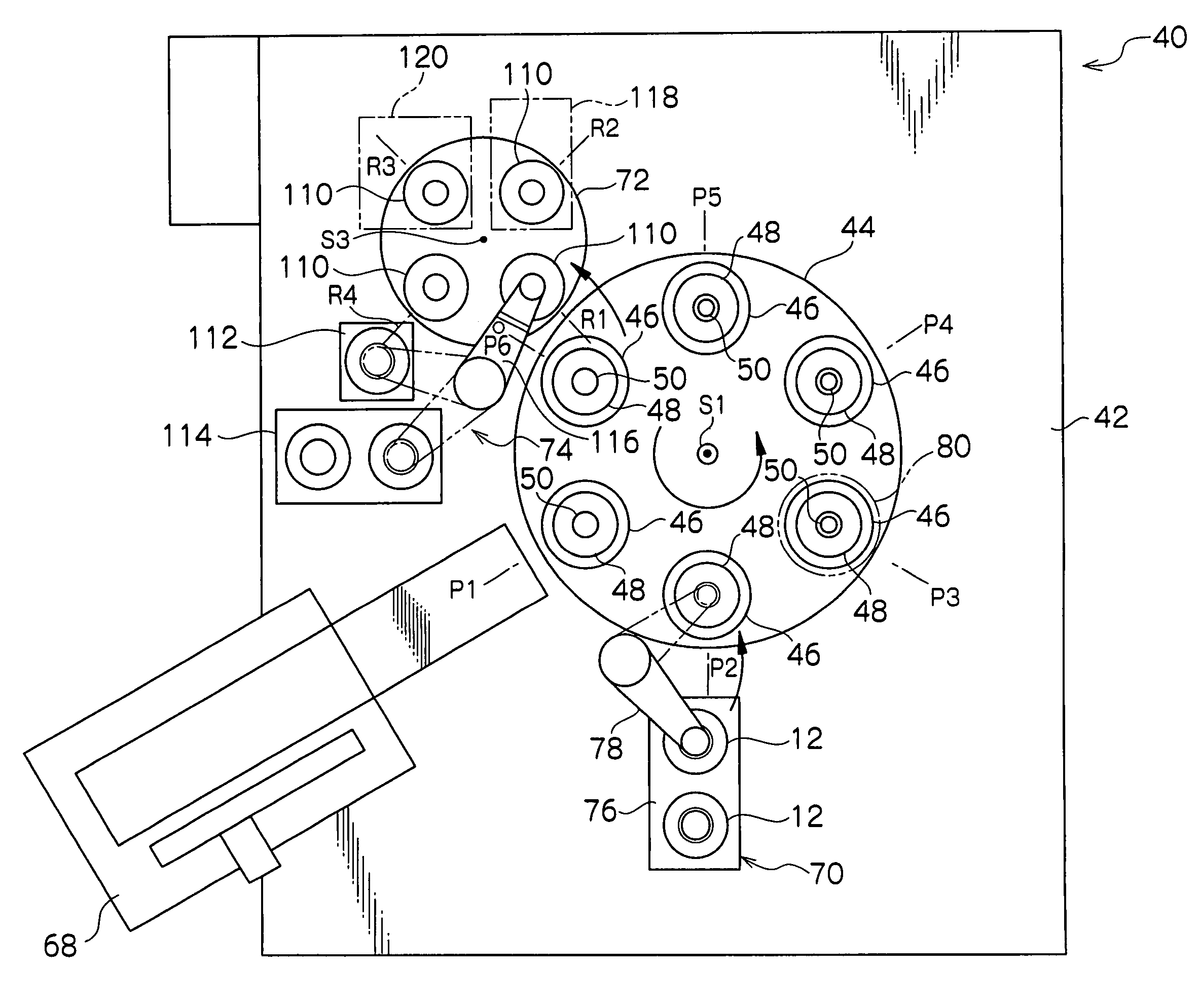
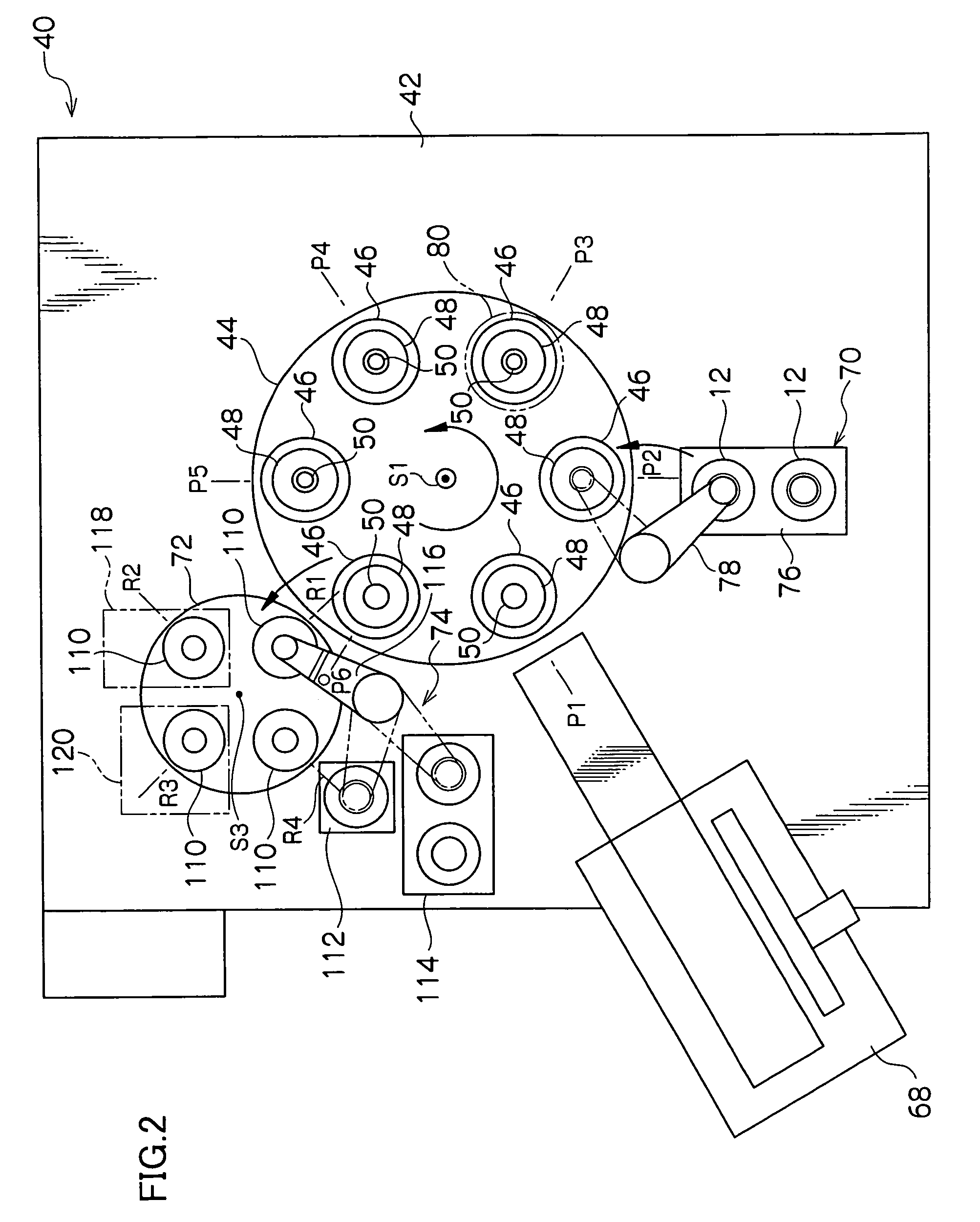
The present invention provides an alignment device for fabricating an optical disc that can accurately align the center of the cover sheet and the center of the disc substrate with each other. This is achieved by inserting a center pin into the cover sheet and the center hole of the disc substrate, and using an alignment lever to push the inner peripheral surface of the cover sheet and the inner peripheral surface of the disc substrate in the same alignment direction. This alignment device can eliminate play between the inner and outer surfaces of the cover sheet and the disc substrate, resulting in high dimensional accuracy of the center alignment.

Problems solved by technology

Therefore, the beam spot is blurred even with slight inclination, thereby making it impossible to achieve recording and reproduction at a high density.
In this state, the entire adhesive film is not uniformly brought into contact with the recording surface of the disc substrate, and therefore, the cover sheet is not joined to the disc substrate by satisfactory joining force.
Therefore, problems arise since the above-described optical disc fabricating apparatus includes a complicated mechanism (i.e., an alignment mechanism) for aligning the center of the cover sheet and the center of the disc substrate with each other with the satisfactory accuracy.
Furthermore the time required, for aligning the center of the cover sheet and the center of the disc substrate with each other with satisfactory accuracy, becomes long.

Method used


Image

  • Alignment device for fabricating optical disk
  • Alignment device for fabricating optical disk
  • Alignment device for fabricating optical disk

Examples


Embodiment Construction

[0036]An optical disc fabricating apparatus in a preferred embodiment according to the present invention will be described below in reference to the attached drawings.

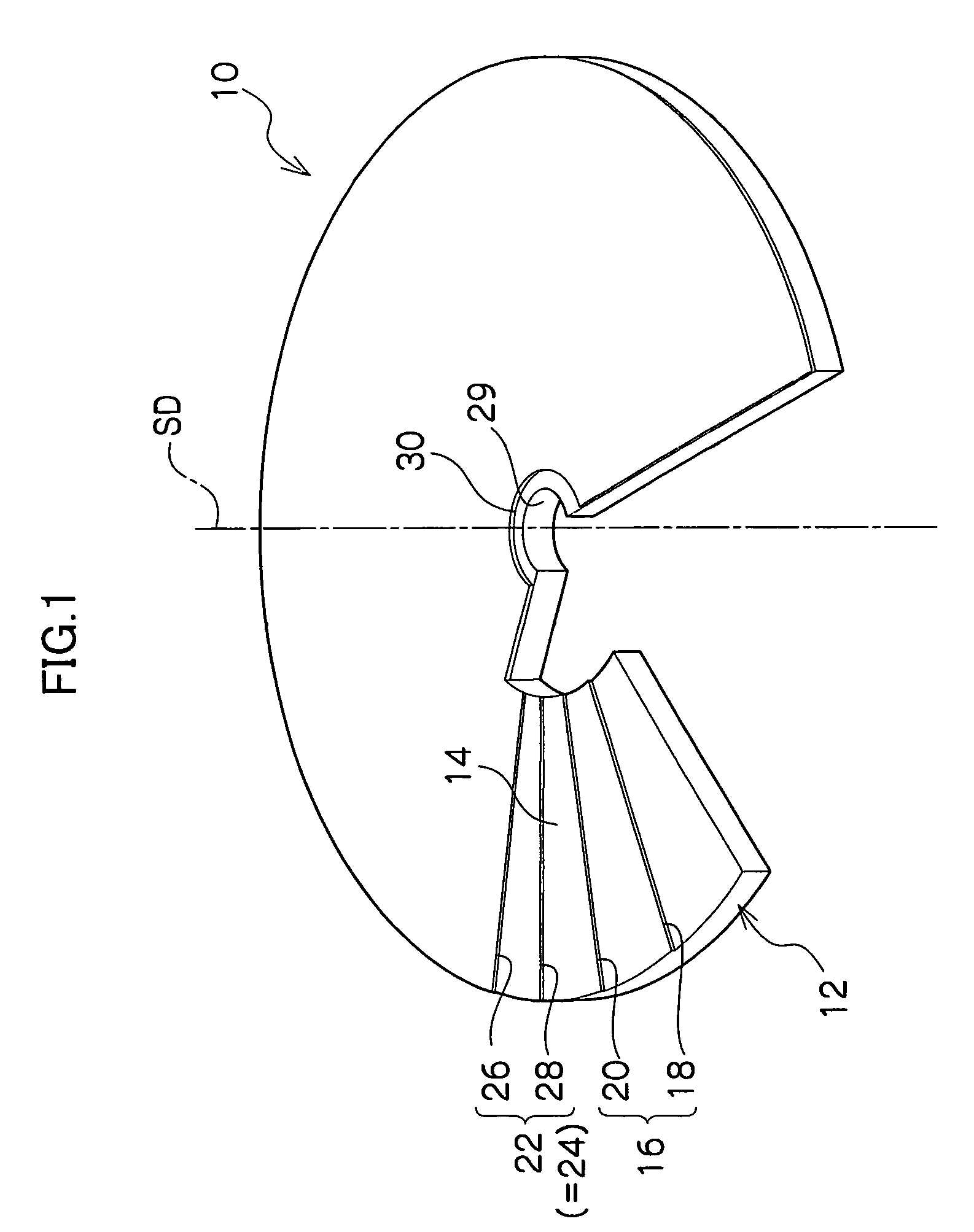
[0037]First of all, a description will be given of the configuration of an optical disc fabricated by an optical disc fabricating apparatus in a preferred embodiment according to the invention. FIG. 1 shows an optical disc fabricated by an optical disc fabricating apparatus in a preferred embodiment according to the invention. On this optical disc 10 can be recorded information at a density higher than that in an optical disc such as a DVD-R in the prior art. For example, in comparison with a conventional optical disc, it is assumed that a blue violet laser beam of a shorter wavelength is used as a recording and reproducing laser beam, and further, that a one-side recording capacity of the optical disc 10 having a diameter of 12 cm is increased up to about 27 Gbyte by increasing the aperture number NA of an objective l...


PUM

PropertyMeasurementUnit
diameteraaaaaaaaaa
thicknessaaaaaaaaaa
thicknessaaaaaaaaaa

Abstract

In an optical disc fabricating apparatus, when the disc substrate is lowered from the tip of a disc inserting portion at a center pin down to a disc supporting portion, a disc urging portion of an alignment lever is pressed by a disc substrate, to be thus pushed in toward an inner periphery and a sheet urging portion is pushed out toward an outer periphery, so as to press the inner peripheral surface of a cover sheet so that both of the cover sheet and the disc substrate are urged in an alignment direction. Thus, it is possible to eliminate play generated between the inner peripheral surface of the cover sheet and the outer peripheral surface of a sheet inserting portion and play generated between the inner peripheral surface of the disc substrate and the outer peripheral surface of the disc inserting portion.

Description

CROSS-REFERENCE TO RELATED APPLICATION[0001]This application claims priority under 35 USC 119 from Japanese Patent Application No. 2004-029323, the disclosure of which is incorporated by reference herein.BACKGROUND OF THE INVENTION[0002]1. Field of the Invention[0003]The present invention relates to an alignment device for fabricating an optical disc, in which the center of a thin film-like cover sheet is aligned with the center of a disc substrate when an optical disc is fabricated by sticking the cover sheet onto a recording surface of the disc substrate.[0004]2. Description of the Related Art[0005]Already widespread are optical discs such as CD-R (Compact Disc-Recordable), CD (Compact Disc), DVD (Digital Versatile Disc), and DVD-R (Digital Versatile Disc-Recordable) for recording or reproducing information by the use of a laser beam. In recent years, storage of increasing quantities of information, such as video information, has been demanded for optical discs, and therefore, hig...

Claims


Application Information

Patent Timeline
Patent Type & Authority Patents(United States)
IPC IPC(8): B32B37/00B29C65/00B29C65/48G11B7/26B29C65/78B32B1/00B32B38/18
CPCB29C65/48B29C66/001B29C66/452B29C66/82661B32B38/1841G11B7/26G11B7/265B29C65/7811B29C65/00Y10T156/1744B29C65/7882B29L2017/005B32B2429/02Y10T156/17B29C66/934B29C66/939B29C66/8322B29C66/71B29C66/8242B29C66/723B29C66/1122B29K2067/003B29K2069/00
Inventor MIZUTA, AKIRA
Owner FUJIFILM HLDG CORP
Learn More