Modulating retroreflector array using vertical cavity optical amplifiers

a technology of vertical cavity optical amplifier and retroreflector array, which is applied in the direction of semiconductor amplifier structure, instrumentation, laser details, etc., can solve the problems of low efficiency, high cost, and large capacitance, and achieves higher extinction ratio, higher speed, and favorable trade-off between range and speed and mrr area

Inactive Publication Date: 2008-03-04
EPITAXIAL TECH
View PDF13 Cites 6 Cited by
  • Summary
  • Abstract
  • Description
  • Claims
  • Application Information

AI Technical Summary

Benefits of technology

[0010]3. Optical amplifier (VCSOA) material and device structures for high active layer gain and low resistance mirror material that will result in high optical gain and low operating power.
[0012]5. Optically preamplified MRR architecture that will enable the best trade-off between MRR size, speed, and range and extinction ratio.
[0014]Use of a VCSOA in place of a standard multi-quantum well (MQW) modulator based passive MRR or in conjunction with an MRR is desirable because the gain enables an extremely favorable trade-off between the range, speed and the MRR area. For example, large area format arrays with diameters of 1 cm are needed for Free Space Optics (FSO). The speeds of such MRRs are only 1-10 Mbps. The extinction ratio of such a device is at best only 10:1. By applying our VCSOA technology to MRRs, either as active MRR or as optically preamplified MRRs, higher speeds, higher extinction ratios and longer ranges can be enabled for the same transmit power. Alternatively, it reduces the power requirement so that lower transmit powers are needed for currently possible ranges and speed.

Problems solved by technology

Although various modulating retro-reflectors such as the multiple quantum well (MQW) retroflectors, micro-electro-mechanical corner cube retroreflector, ferroelectric liquid crystal modulator, thin film diffractive modulating retroreflector, have been demonstrated (1,2,3), their performance is still limited to lower bandwidths and short haul ranges.
One of the main drawbacks of current MRRs is the relatively large capacitance resulting from the need for large area and high retroreflected power.
In addition, the high series resistance needed for large modulation depths limits the bandwidth Other drawbacks are: high cost, high losses, slow speed, limited bandwidth, low reflection efficiency.
However, the MRRs based on MQWs are passive and have as much a 3 dB reflective loss.

Method used


Image

  • Modulating retroreflector array using vertical cavity optical amplifiers
  • Modulating retroreflector array using vertical cavity optical amplifiers
  • Modulating retroreflector array using vertical cavity optical amplifiers

Examples


Embodiment Construction

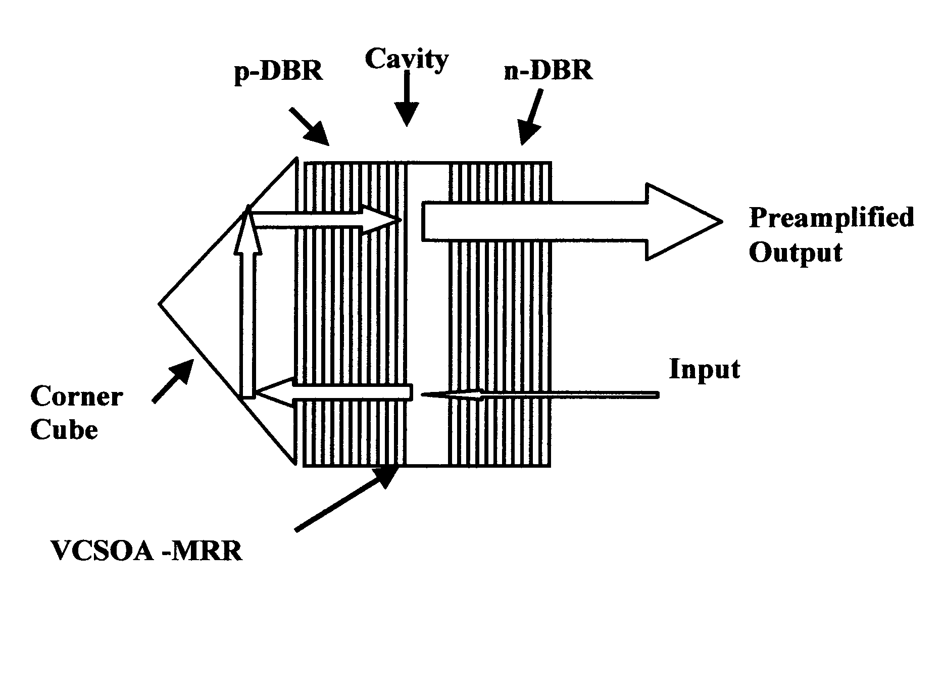
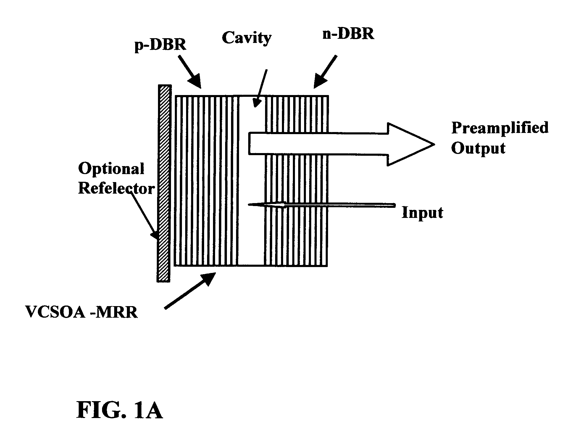
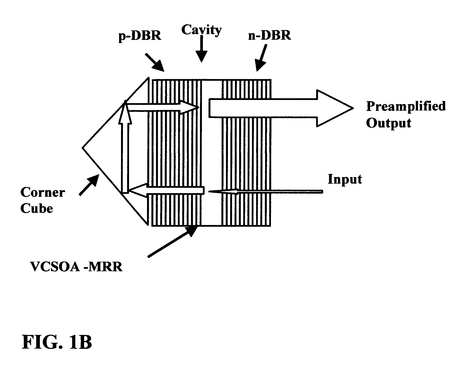
[0022]FIG. 1 shows the basic VCSOA MRR concept of the present invention. The approach builds on technologies described in the copending U.S. patent application Ser. No. 10 / 621,203. The basic pixel of the proposed active MRR is a VCSOA which is operated in the reflective mode. The same VCSOA when operated in the transmissive mode is used to produce the optical amplification. For MRR applications, the VCSOA is designed differently to have optimized reflective gain rather than the transmissive gain as with the VCSOA photoreceiver (U.S. patent application Ser. No. 10 / 621,203). For the latter, the number of bottom mirrors bounding the VCSOA boundary is minimized for maximum transmissive output, while for the active MRR, the number of top mirrors is minimized.

[0023]FIG. 2 shows a 128×128 active MRR array sample, based on VCSOA arrays which can be bump bonded onto readout circuits to produce an MRR with reflective gain. Each pixel will have 20-100 μm diameter with 10 μm spacing between pix...


PUM


Abstract

A vertical cavity semiconductor optical photoamplifer (VCSOA) is used as a modulating retro-reflector (MRR) as a pixel in an array. The boundary of the cavity in the VCSOA forms a mirror for reflecting an incident light as an amplified output.

Description

BACKGROUND OF THE INVENTION[0001]1. Field of the Invention[0002]This invention relates to vertical cavity semiconductor optical amplifier (VCSOA) technology for free space optical communication, in particular to arrays of active modulating retro-reflectors.[0003]2. Brief Description of Prior Art[0004]In a co-pending U.S. patent application Ser. No. (10 / 621,208), it has been disclosed that photoreceivers using vertical cavity semiconductor optical amplifiers (VCSOA) as optical preamplifiers is capable of quantum limit sensitivities for free space optical communications networks. It has also been disclosed that all the components of a photoreceiver-optical amplifier, optical band-pass filter, and photodiode module can be monolithically integrated on a single chip. In this invention, we apply the optical preamplified receiver technology to modulating retro-reflectors (MRR), either as active MRR or as optically preamplified MRRs with which higher speeds, higher extinction ratios and lon...

Claims


Application Information

Patent Timeline
Patent Type & Authority Patents(United States)
IPC IPC(8): H01S3/00
CPCG02B5/122G02B26/001G02F2203/70H01S3/08059H01S5/18305H01S5/18386H01S5/50
Inventor FATHIMULLA, AYUB MOHAMMEDHIER, HARRY STEPHENAINA, OLALEYE A.
Owner EPITAXIAL TECH
Why Eureka
Try Eureka