Liquid raw material supply unit for vaporizer

a technology for supplying units and vaporizers, which is applied in the direction of engine diaphragms, valve housings, diaphragm valves, etc., can solve the problems of clogging the nozzle of the vaporizer, reducing the yield ratio, and reducing so as to reduce the liquid remaining or staying zone, the effect of enhancing the replacement rate of residual liquid

Active Publication Date: 2008-03-18
CKD +1
View PDF6 Cites 7 Cited by
  • Summary
  • Abstract
  • Description
  • Claims
  • Application Information

AI Technical Summary

Benefits of technology

[0013]The present invention has been made in view of the above circumstances and has an object to provide a liquid raw material supply unit in a miniaturized and integrated design with simple passage configurations, capable of reducing liquid remaining or staying zones, thereby enhancing a replacement rate of residual liquid.

Problems solved by technology

Such deposits are likely to cause various problems; e.g., they become a particle generation source, leading to a lower yield ratio, they clog control valves and line pipes, or they clog nozzles of the vaporizer.
This construction disadvantageously needs a large mounting space, which could impede miniaturization and high integration.
Thus, a replacement rate (or replacement capability) of the residual or remaining liquid (a liquid-liquid replacement rate and a liquid-gas replacement rate) is poor, which needs much time for replacement of the residual liquid, resulting in a longer cleaning time.
This also leads to a prolonged cycle time of a semiconductor manufacturing device and hence a lower manufacturing efficiency.
Further, the liquid-gas replacement rate is extremely poor with the result that the cleaning solution remaining after cleaning could not be replaced completely by the purge gas.
However, the monoblock valves X1 to X4 used in the line have very complicated flow passages respectively.

Method used


Image

  • Liquid raw material supply unit for vaporizer
  • Liquid raw material supply unit for vaporizer
  • Liquid raw material supply unit for vaporizer

Examples


Embodiment Construction

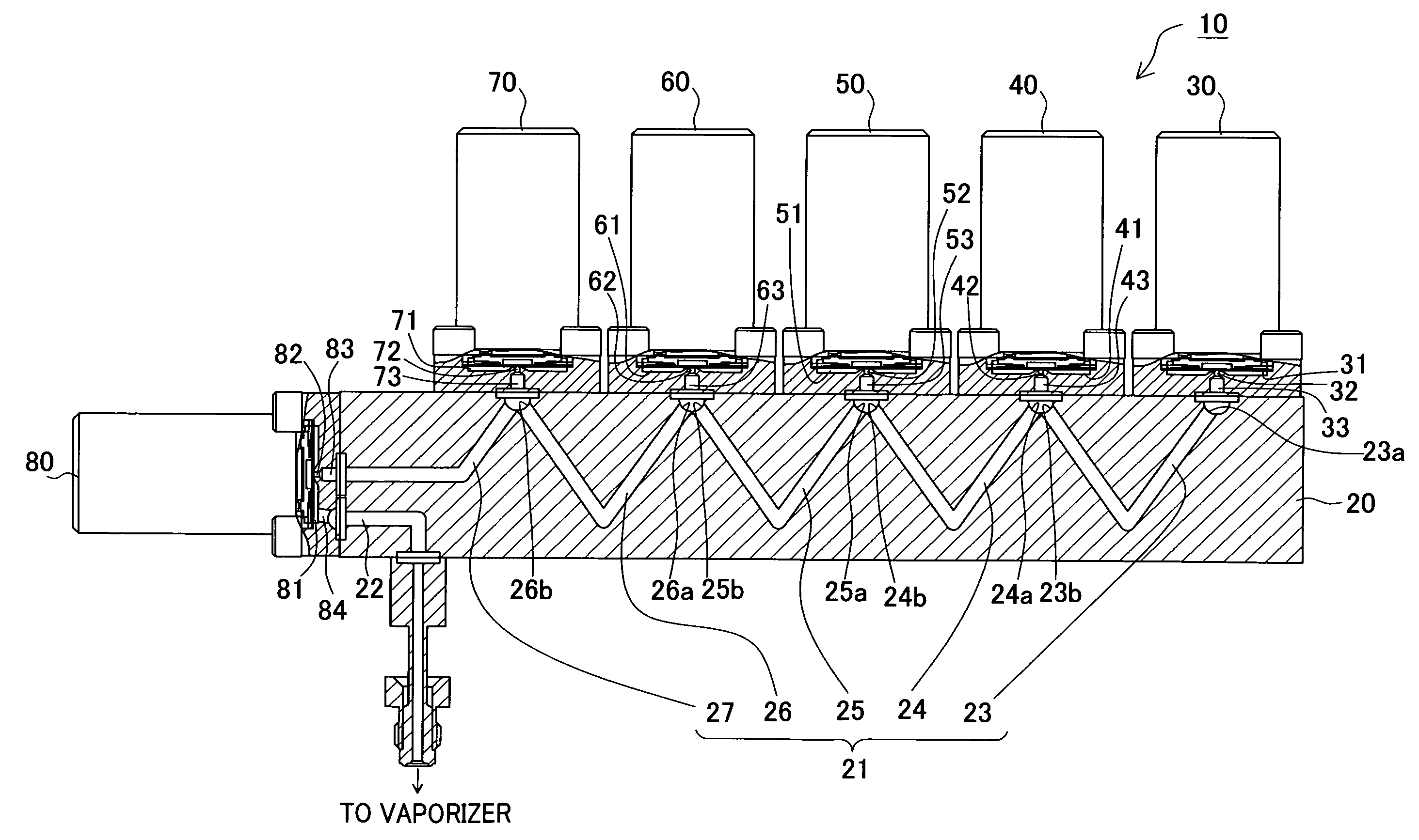
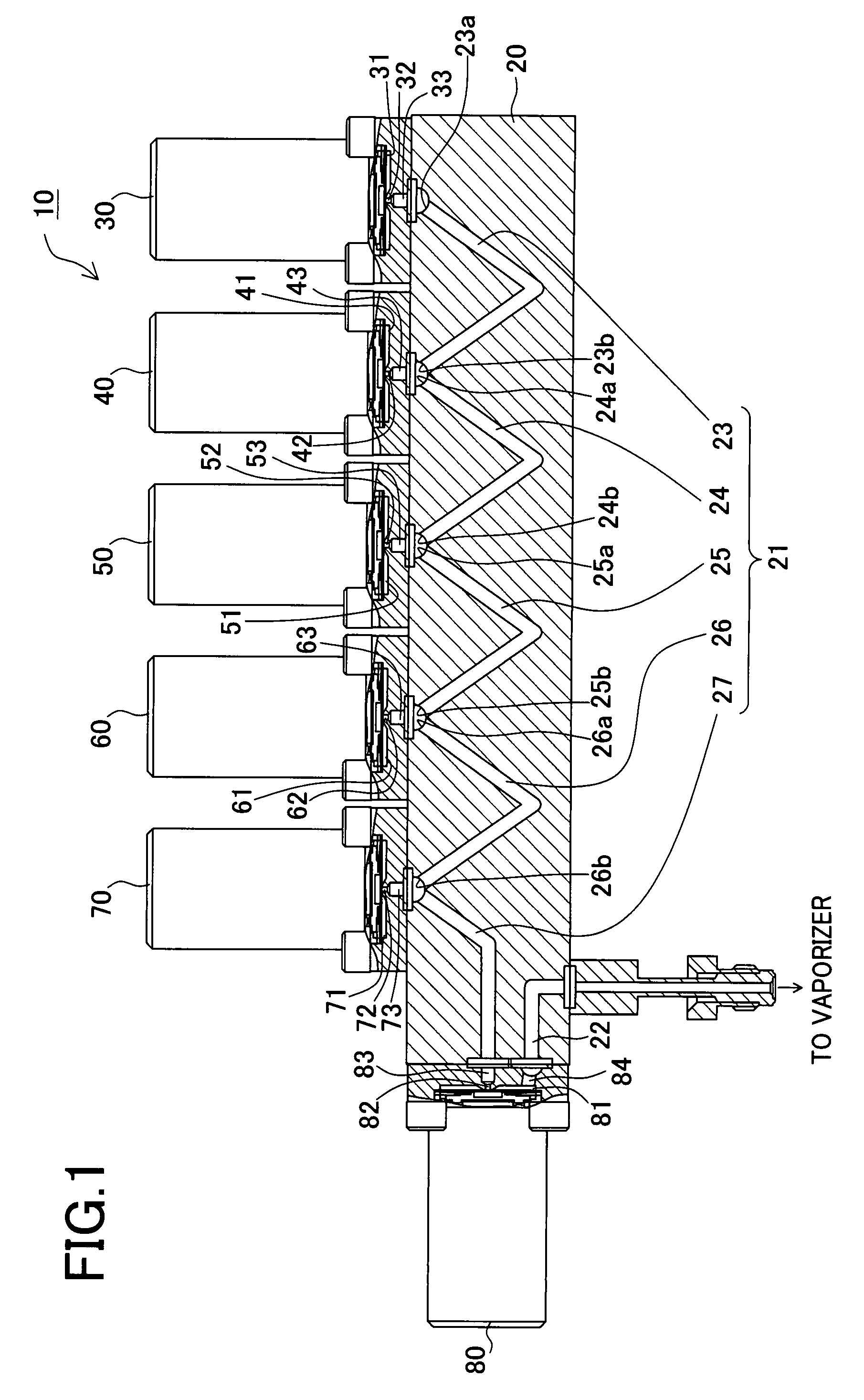
[0025]A detailed description of a preferred embodiment of a liquid raw material supply unit for a vaporizer according to the present invention will now be given referring to the accompanying drawings. The configuration of the liquid raw material supply unit of the present embodiment will be explained referring to FIG. 1. FIG. 1 is a partially sectional view showing a schematic configuration of the liquid raw material supply unit of the present embodiment.

[0026]The liquid raw material supply unit 10 includes a purge gas supply valve 30, a cleaning solution supply valve 40, a first liquid raw material supply valve 50, a second liquid raw material supply valve 60, and an introducing valve 70 connectable to a drain (hereinafter, referred to as a “drain introducing valve”, which corresponds to a second introducing valve of the present invention), which are fixedly mounted in line on the upper surface of a manifold 20 internally formed with flow passages, as shown in FIG. 1. Further, an i...


PUM


Abstract

A liquid raw material supply unit for a vaporizer is adapted to supply a liquid raw material to the vaporizer that vaporizes the liquid raw material. The unit comprises: a manifold internally formed with a flow passage; and a plurality of fluid control valves mounted on the manifold, wherein the plurality of fluid control valves includes: a liquid raw material control valve for controlling supply of the liquid raw material to the flow passage; a cleaning solution control valve for controlling supply of a cleaning solution to the flow passage; a purge gas control valve for controlling supply of a purge gas to the flow passage; and a first introducing control valve connectable to the vaporizer for controlling supply of a fluid from the flow passage to the vaporizer, the purge gas control valve, the cleaning solution control valve, the liquid raw material control valve, and the first introducing control valve being mounted on the manifold in this order from an upstream side of the manifold, wherein the flow passage is connected to valve ports of the plurality of control valves respectively, the valve ports communicating with valve openings of the respective control valves, and the flow passage is configured to allow the purge gas supplied from the purge gas control valve to directly flow in the valve ports of the cleaning solution control valve and the liquid raw material control valve placed downstream from the purge gas control valve.

Description

BACKGROUND OF THE INVENTION[0001]1. Field of the Invention[0002]The present invention relates to a liquid raw material supply unit for a vaporizer for supplying a liquid raw material to the vaporizer.[0003]2. Description of Related Art[0004]In recent years, a high-integration design has been demanded for semiconductor memory devices and embedded memory LSIs using capacitors such as DRAM (Dynamic Random Access Memory) and FeRAM (Ferroelectric Random Access Memory). In response to such demands, high dielectric constant materials have to be used for manufacture of semiconductors. The high-dielectric materials are often used in liquid state. In many cases, accordingly, a liquid raw material is supplied to a vaporizer in which the liquid raw material is vaporized, and this vaporized gas is supplied to a reactor. This process therefore needs a liquid raw material supply line for supplying the liquid raw materials to the vaporizer.[0005]If the liquid raw material remains in the liquid raw ...

Claims


Application Information

Patent Timeline
Patent Type & Authority Patents(United States)
IPC IPC(8): F16K51/00
CPCF16K7/14F16K27/003F16K31/06H01L21/31691Y10T137/87885Y10T137/4259H01L21/02
Inventor OKABE, TSUNEYUKIOKURA, SHIGEYUKIDOI, HIROKIITO, MINORUMORI, YOJINISHIMURA, YASUNORI
Owner CKD
Why Eureka
Try Eureka