
Exhaust gas catalytic converter

a catalytic converter and exhaust gas technology, applied in physical/chemical process catalysts, metal/metal-oxide/metal-hydroxide catalysts, separation processes, etc., can solve the problem of sintered catalytic precious metal particles

Inactive Publication Date: 2008-03-18
MAZDA MOTOR CORP
View PDF25 Cites 10 Cited by
  • Summary
  • Abstract
  • Description
  • Claims
  • Application Information

AI Technical Summary

Benefits of technology

The present invention relates to an exhaust gas catalytic converter that improves its performance by enhancing the oxygen storage capacity and thermal resistance of the upstream and downstream catalysts. This is achieved by doping the oxygen storage component in the upstream catalyst with Rh atoms, which increases its oxygen storage capacity and prevents the structure from breaking down under the heat of exhaust gas. The downstream catalyst can also be doped with Rh atoms, but to a lesser extent. The first solution involves using an oxygen storage component with a structure in which Rh atoms are placed at or between crystal lattice points of a mixed oxide containing Ce and Zr. The second solution involves using an oxygen storage component with a structure in which Rh atoms are placed at or between crystal lattice points of a Ce—Zr binary oxide. The third solution involves using an oxygen storage component with a structure in which Rh atoms are placed at or between crystal lattice points of a Ce—Zr—Nd ternary oxide. These solutions improve the exhaust gas purification performance, downsize the catalytic converter, and enhance the arrangeability of the catalytic converter.

Problems solved by technology

Therefore, the underfloor catalysts have a problem that catalytic precious metal particles are sintered by the heat of the exhaust gas, like the close-coupled catalyst.

Method used


Image

  • Exhaust gas catalytic converter
  • Exhaust gas catalytic converter
  • Exhaust gas catalytic converter

Examples


Embodiment Construction

[0045]An embodiment of the present invention will be described in details below with reference to the drawings.

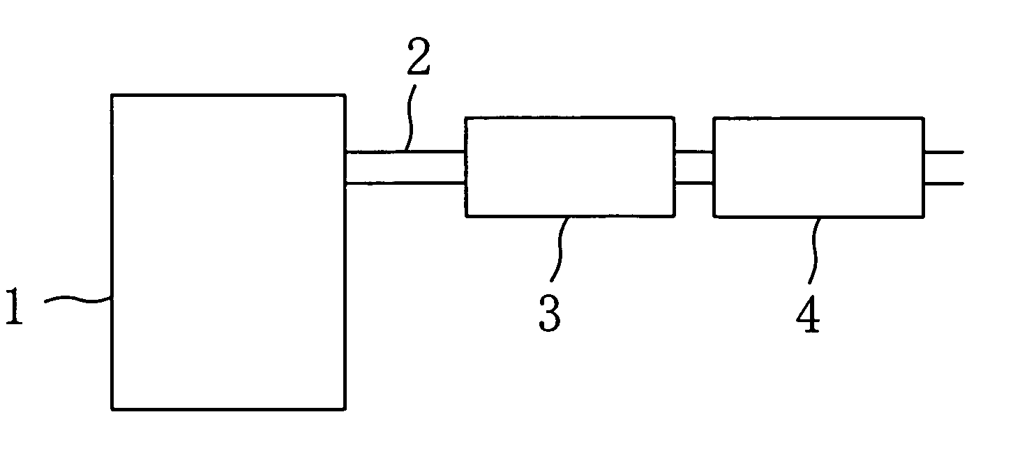
[0046]In FIG. 1, the reference numeral 1 denotes an automobile engine, the reference numeral 2 denotes an exhaust passage of the engine, the reference numeral 3 denotes an upstream catalyst (three-way catalyst) arranged in an upstream side of the exhaust passage 2 through which exhaust gas flows, and the reference numeral 4 denotes a downstream catalyst (three-way catalyst) arranged in a downstream side of the exhaust passage 2.

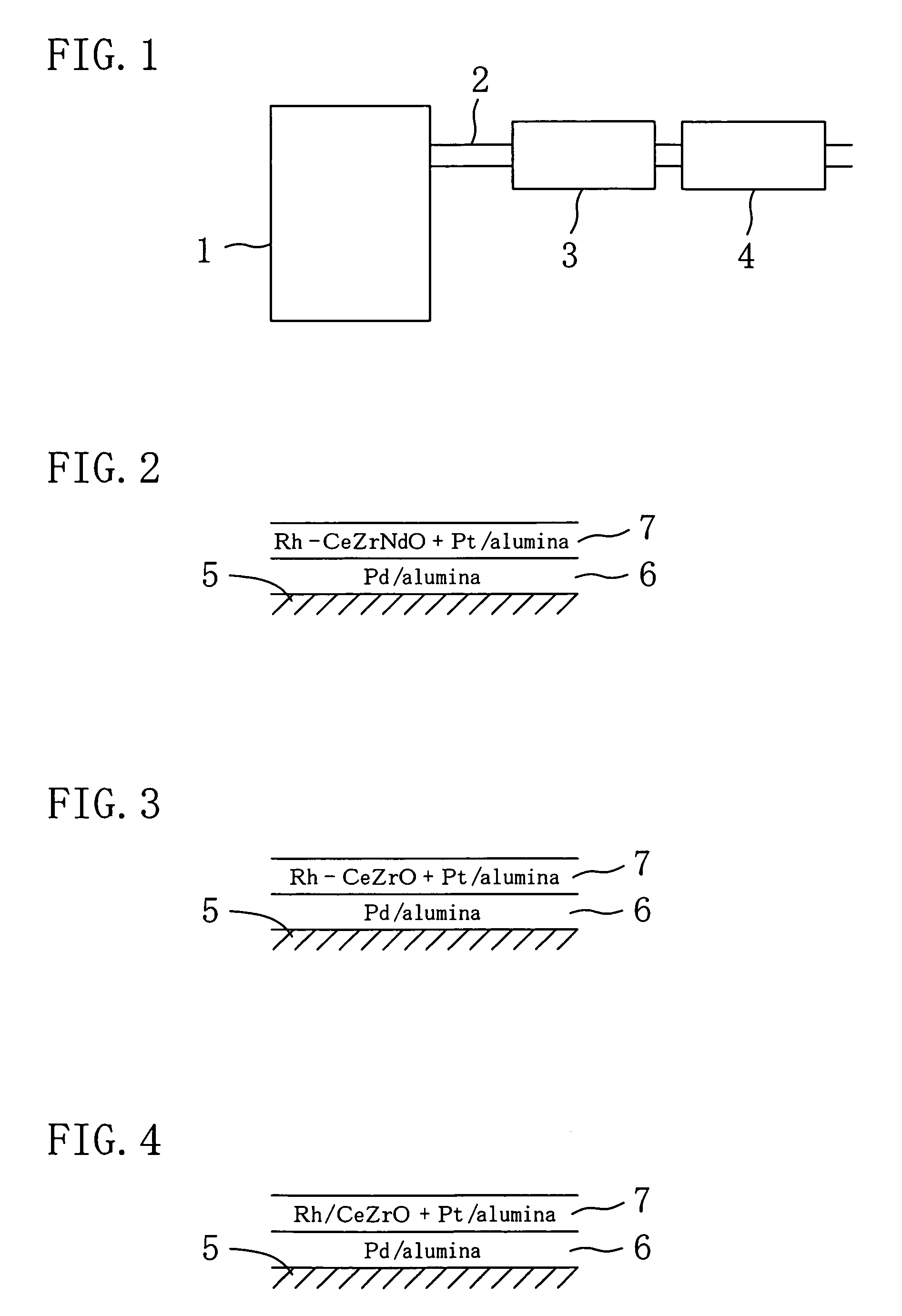
[0047]In order to construct each of catalytic converters of Examples and Comparative Example using the catalyst arrangement shown in FIG. 1, three types of catalysts A, B and C shown in FIGS. 2, 3 and 4, respectively, were prepared. The three types of catalysts were each formed by stacking an inner catalytic layer 6 and an outer catalytic layer 7 on the wall 5 of each of cells forming a honeycomb support (hereinafter, simply referred to as a support)...


PUM

PropertyMeasurementUnit
frequenciesaaaaaaaaaa
total volumeaaaaaaaaaa
temperatureaaaaaaaaaa

Abstract

The present invention is intended to ensure the improvement in catalytic performance of an exhaust gas catalytic converter, which is an essential performance thereof, ensure the thermal resistance thereof and downsize the converter, i.e., improve the arrangeability thereof. The exhaust gas catalytic converter has an upstream catalyst and a downstream catalyst which are arranged in upstream and downstream sides of an engine exhaust passage through which exhaust gas flows. Each of the upstream catalyst and the downstream catalyst contains an oxygen storage component. The oxygen storage component in the upstream catalyst has a structure in which Rh atoms are placed at or between crystal lattice points of a mixed oxide containing Ce and Zr and has a larger amount of oxygen storage than the oxygen storage component in the downstream catalyst under the same temperature conditions.

Description

CROSS-REFERENCES TO RELATED APPLICATIONS[0001]This application claims priority under 35 USC 119 to Japanese Patent Application No. 2005-116627, the entire contents of which are incorporated herein by reference.BACKGROUND OF THE INVENTION[0002](a) Field of the Invention[0003]This invention relates to exhaust gas catalytic converters useful for purifying exhaust gas from automobile engines.[0004](b) Description of the Related Art[0005]Many of recent automobile exhaust gas purification techniques use a close-coupled catalyst (manifold catalyst) directly coupled to an exhaust manifold for early catalytic activation after engine start, in combination with one or more underfloor catalysts disposed under the vehicle floor to convert part of exhaust gas which the close-coupled catalyst has failed to convert. Such underfloor catalysts are also disposed as close to the engine as possible for their early catalytic activation. Therefore, the underfloor catalysts have a problem that catalytic pr...

Claims


Application Information

Patent Timeline
Patent Type & Authority Patents(United States)
IPC IPC(8): B01J2/10B01D50/00
CPCB01D53/945F01N13/0093B01J23/002B01J23/63B01J35/0006B01J37/0244B01J37/03F01N3/0814B01D53/9454F01N13/009B01D2255/407B01J21/066B01J37/0248B01J2523/00F01N2370/02F01N2510/06F01N2570/16Y02T10/22B01J2523/3712B01J2523/3725B01J2523/48B01J2523/822Y02T10/12B01J35/19
Inventor MIYOSHI, SEIJIYAMADA, HIROSHITAKAMI, AKIHIDE
Owner MAZDA MOTOR CORP
Learn More