Transducer package for process control

a technology of transducer and process control, which is applied in the direction of resistance/reactance/impedence, frequency selective voltage/current level measurement, instruments, etc., can solve the problem of wide-scale proliferation of this technology, the influence of load linearity, and the creation of prevalent harmonic distortion

Active Publication Date: 2008-03-18
TURNER TERRY R
View PDF9 Cites 23 Cited by
  • Summary
  • Abstract
  • Description
  • Claims
  • Application Information

AI Technical Summary

Benefits of technology

[0025]In one aspect, a system is provided herein for monitoring the harmonic content of the RF signal delivered to an RF powered device. The system comprises (a) a voltage transducer adapted to sample the voltage of the RF signal and to output a first signal representative thereof, (b) a current transducer adapted to sample the current of the RF signal and to output a second signal representative thereof, and (c) a memory device in communication with at le...

Problems solved by technology

The non-linearity of the load affects the voltage and current sine waves of the delivered RF power by creating prevalent harmonic distortion.
Unfortunately, wide scale proliferation of this technology has not been realized due to several fundamental limitations in the available technology.
One of the most significant limitations in the existing technology has to do with product architecture.
Consequently, it is not possible to replace either package independently of the other without recalibrating the system.
Since downtime is extremely expensive in a semiconductor processing line, this deficiency creates fatal maintenance and support issues for users of these RF sensor based process control solutions.
In each case, the design is not capable of having a replacement substituted for either component package without the necessity to recalibrate the entire RF sensor device (consisting of both the transducer and the analysis/communication packages).
Another issue with existing devices for monitoring the harmonic content of delivered RF power has to do with self-bias voltage.
However, although several voltage sampling schemes have been proposed in the art for monitoring the harmonic content of delivered RF power, to date, none of these schemes also allow the self-bias voltage to be monitored.
A further issue with existing devices for monitoring the harmonic content of delivered RF power concerns the shielding of the inductive transducer.
In addition, the diode-like characteristics of plasmas can cause the RF current flow after ignition to be very high.
The RF power is typically delivered to a capacitively coupled electrode where the flow of DC current is blocked, thus resulting in the DC “self-bias” voltage.
Unfortunately, the use of conventional shields to protect the transducer from ambient stray fields also impedes the measurement of the desired primary RF current magnetic field.
However, none of these designs overcome the above noted infirmity.
U.S. Pat. No. 5,834,931 (Moore et al.) teaches a single turn first principles implementation of Faraday's law which, unfortuna...

Method used


Image

  • Transducer package for process control
  • Transducer package for process control
  • Transducer package for process control

Examples


Embodiment Construction

[0051]Preferred embodiments of the present invention are illustrated in the FIGURES, like numerals being used to refer to like and corresponding parts of the various drawings.

1. RF SENSOR FOR PROCESS CONTROL

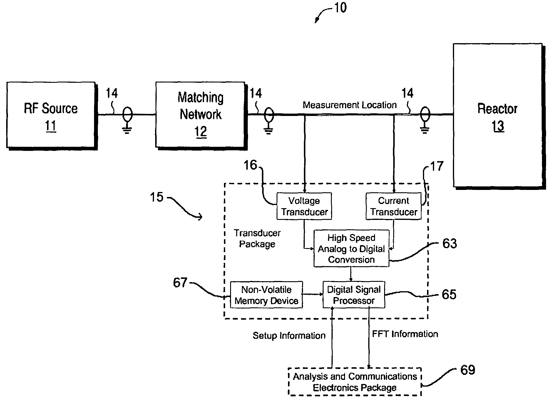
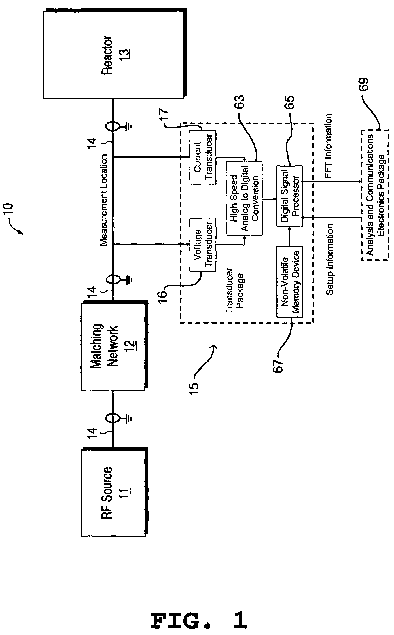
[0052]Referring to FIG. 1, a block diagram showing a utilization of an RF sensor in an RF controlled device made in accordance with the teachings herein is shown. In this exemplary system 10, an electrical source in the form of an RF generator 11 (RF source) is coupled to a processing reactor 13 through a matching network 12 by transmission line 14. The reactor 13 can be of a variety of reactors, such as a plasma reactor, for processing a variety of materials, including semiconductor wafers. Moreover, one skilled in the art will appreciate that a variety of processing systems utilizing electrical or microwave energy (including RF) sources are known to the art, and that any one of these systems, or various combinations of such systems, can be utilized in the practice of the teachi...


PUM

PropertyMeasurementUnit
Electric impedanceaaaaaaaaaa
Electric potential / voltageaaaaaaaaaa
Efficiencyaaaaaaaaaa

Abstract

A system (10) is provided herein for monitoring the harmonic content of the RF signal delivered to an RF powered device (13). The system comprises (a) a voltage transducer (16) adapted to sample the voltage of the RF signal and to output a first signal representative thereof, (b) a current transducer (17) adapted to sample the current of the RF signal and to output a second signal representative thereof, and (c) a memory device (67) in communication with at least one, and preferably both, of the aforementioned transducers 16 and 17 and which contains calibration information specific to the transducers.

Description

CROSS REFERENCE TO RELATED APPLICATIONS[0001]This application claims priority to U.S. Ser. No. 60,468,414, filed May 6, 2003, entitled “RF Sensor Voltage Transducer,” U.S. Ser. No. 60 / 468,412, filed May 6, 2003, entitled “RF Detector for Semiconductor Processing,” U.S. Ser. No. 60 / 468,413, filed May 6, 2003, entitled “RF Sensor Current Transducer,” U.S. Ser. No. 60 / 486,983, filed Jul. 14, 2003, entitled “RF Power Sensor for Known Fixed Impedance Environments” U.S. Ser. No. 60 / 487,745, filed Jul. 16, 2003, entitled “An RF Delivery Diagnostic System,” and U.S. Ser. No. 60 / 412,752, filed Sep. 23, 2002, entitled “RF Sensor for Process Control.”TECHNICAL FIELD OF THE INVENTION[0002]The present invention relates generally to monitoring the harmonic content of delivered RF power, and more particularly, a system and method for monitoring the harmonic content of delivered RF power.BACKGROUND OF THE INVENTION[0003]Plasma etch and deposition processes have become the dominant pattern transfer ...

Claims


Application Information

Patent Timeline
IPC IPC(8): H01J7/24G01R15/14G01R15/16G01R15/18G01R23/20G01R27/04G01R35/00
CPCG01R19/0007G01R19/0061H01J37/32174H01J37/32935G01R19/0053
Inventor TURNER, TERRY R.
Owner TURNER TERRY R
Why Eureka
Try Eureka