Resistor-less accurate low voltage detect circuit and method for detecting a low voltage condition

a low voltage detection and resistorless technology, applied in the field of resistorless accurate low voltage detection circuit and low voltage condition detection method, can solve the problems of large resistors, inability to utilize the same low voltage detection circuit on a number of different integrated circuit chips having different layouts, and inability to meet the latest generation of devices and systems. achieve the effect of saving current and die area consumption

Active Publication Date: 2008-03-25
CYPRESS SEMICON CORP
View PDF11 Cites 32 Cited by
  • Summary
  • Abstract
  • Description
  • Claims
  • Application Information

AI Technical Summary

Benefits of technology

[0014]In one aspect, the invention is directed to a low voltage detect circuit for detecting when an external voltage (Vext) drops below a predetermined minimum voltage. In general, the low voltage detect circuit described herein may be configured to detect a low voltage condition based on a threshold voltage difference between a transistor with a substantially non-zero threshold voltage, hereinafter referred to as a “non-zero threshold transistor,” and a transistor with a threshold voltage relatively close to zero, hereinafter referred to as a “zero threshold transistor”. According to a particularly advantageous aspect of the invention, the low voltage detect circuit described herein comprises substantially no resistors or reference voltage generation circuits, and therefore, provides significant savings in both current and die area consumption.

Problems solved by technology

Although satisfactory for a number of applications in the past, the above approach is not wholly satisfactory for the latest generation of devices and systems for a number of reasons.
One significant disadvantage of the above circuit is that large resistors, e.g., in the range of 1.5 to 15 mega-ohms (MΩ) or more, may be required to reduce the standby current through the resistor divider network.
However, the large size of the resistors can make it difficult to utilize the same low voltage detect circuit on a number of different Integrated Circuit (IC) chips having different layouts.
In addition, relatively large amounts of standby current may still be dissipated even when large resistors are used in the resistor divider network.
The relatively large standby current can make the circuit unsuitable for a number of low-power or battery powered applications, including memory used in mobile devices, such as MoBL™ SRAM (Static Random Access Memory), a commercially available product from Cypress Semiconductor of San Jose, Calif.
Moreover, due to layout area constraints on the chips, it is generally not possible to increase the resistances within the resistor divider network to effectively reduce the standby current.
In other words, layout constraints on a given IC chip may limit the size of the resistors that may be used in the divider network, thereby limiting the potential reduction in standby current.
Another disadvantage of LVD circuit 100 is the need for a stable reference voltage generation circuit, such as bandgap circuit 120.
In addition, bandgap circuits tend to become considerably less accurate as the power supply voltage drops to within a few hundred milli-volts of the generated reference voltage.

Method used


Image

  • Resistor-less accurate low voltage detect circuit and method for detecting a low voltage condition
  • Resistor-less accurate low voltage detect circuit and method for detecting a low voltage condition
  • Resistor-less accurate low voltage detect circuit and method for detecting a low voltage condition

Examples


Embodiment Construction

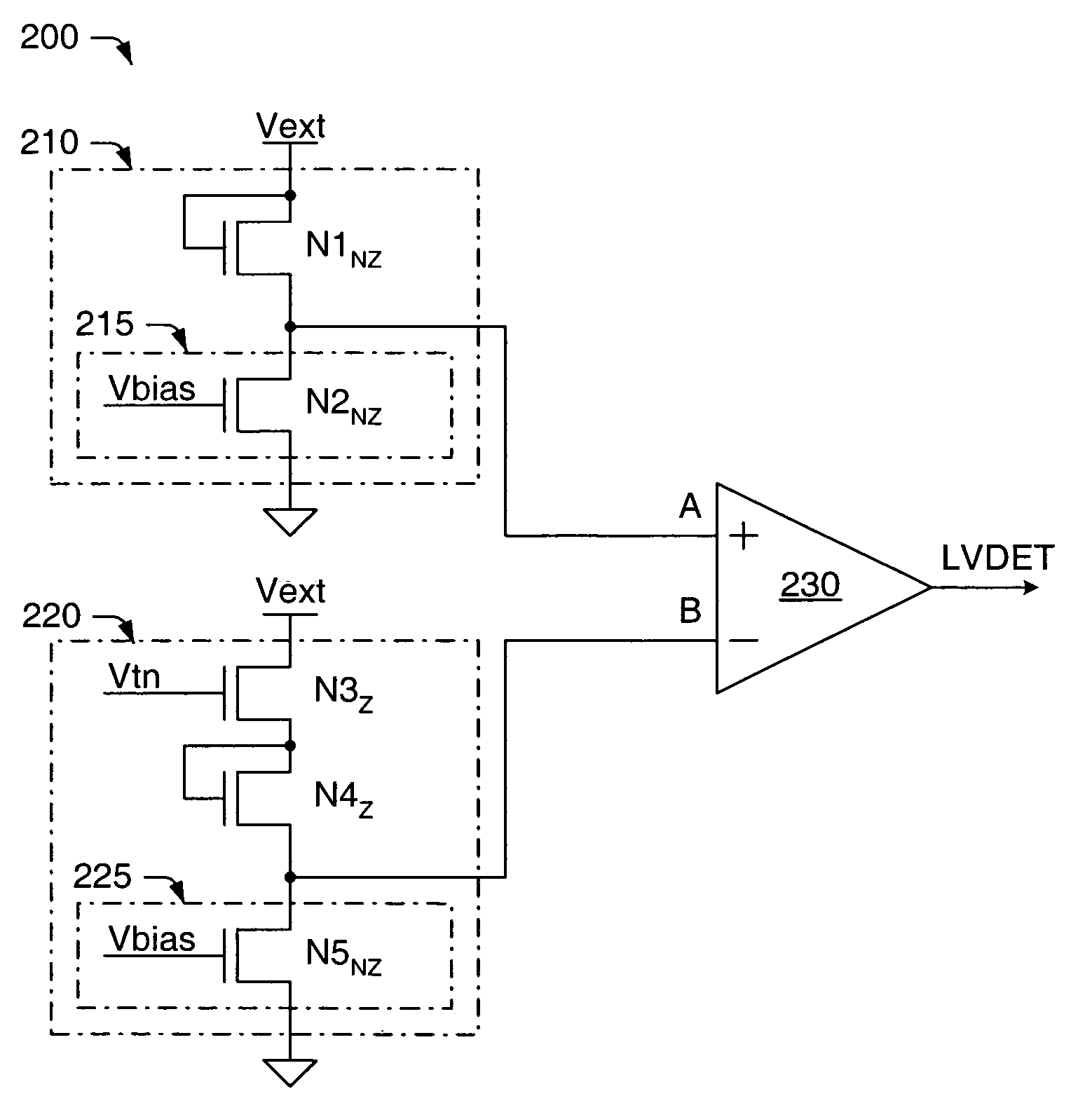
[0021]The present invention is generally directed to a low voltage detect circuit for detecting a drop in voltage from an external power supply below a predetermined minimum threshold voltage. A logic circuit and method according to one embodiment of the present invention will now be described in reference to FIG. 2.

[0022]FIG. 2 is a block diagram of a low voltage detect (LVD) circuit according to one embodiment of the present invention. As shown in FIG. 2, LVD circuit 200 generally includes a first sub-circuit 210, a second sub-circuit 220 and a differential amplifier or comparator 230. The first and second sub-circuits of FIG. 2 each include a plurality of N-channel Metal Oxide Semiconductor (NMOS) transistors, which are coupled in series between an externally supplied voltage (Vext) and ground. Though NMOS transistors are used in the embodiment of FIG. 2 and described herein, one skilled in the art would readily understand how the circuit could be modified to include PMOS transis...


PUM


Abstract

A low voltage detect circuit is provided herein for detecting when an external voltage (Vext) drops below a predetermined minimum voltage. In general, the low voltage detect circuit described herein may be configured to detect a low voltage condition based on a threshold voltage difference between a non-zero threshold transistor having a substantially non-zero threshold voltage, and a zero threshold transistor having a threshold voltage relatively close to zero. According to a particularly advantageous aspect of the invention, the low voltage detect circuit described herein comprises substantially no resistors or reference voltage generation circuits, and therefore, provides significant savings in both current and die area consumption without sacrificing accuracy. The low voltage detect circuit of the present invention is particularly useful in power regulators, such as those used in memory systems or devices.

Description

PRIORITY APPLICATION[0001]This application claims priority to provisional application No. 60 / 531,817 entitled “Resistor-less Accurate Low Voltage Detect Circuit” filed Dec. 22, 2003.BACKGROUND OF THE INVENTION[0002]1. Field of the Invention[0003]The present invention relates generally to semiconductor integrated circuits, and more particularly, to circuits and systems that use low voltage detect circuits for detecting when an external power supply drops below a predetermined minimum voltage. Other embodiments of the invention may relate to a voltage detect circuit capable of detecting alternative voltage levels and / or voltage ranges.[0004]2. Description of the Related Art[0005]The following descriptions and examples are given as background only.[0006]Low voltage detect (LVD) circuits are often included in low-power or battery powered systems, such as portable electronic devices, to detect low-voltage conditions that may harm the low-power system or prevent the low-power system from ...

Claims


Application Information

Patent Timeline
Patent Type & Authority Patents(United States)
IPC IPC(8): H02H3/24H02H3/20H02H9/04H03K5/153H03K5/22
CPCG06F1/28H02H3/24H03K17/223
Inventor MAHEEDHAR, SURYADEVARAKOTHANDARAMAN, BADRINARAYANAN
Owner CYPRESS SEMICON CORP
Why Eureka
Try Eureka