Surface acoustic wave element, method of manufacturing the same and surface acoustic wave device

a surface acoustic wave and acoustic wave element technology, applied in piezoelectric/electrostrictive/magnetostrictive devices, piezoelectric/electrostriction/magnetostriction machines, impedence networks, etc., can solve the problem of inability to obtain the large q value required for resonators, inability to meet frequency characteristics of high-accuracy communication equipment or the like, and inability to achieve characteristics to satisfy specifications

Inactive Publication Date: 2008-04-01
SEIKO EPSON CORP
View PDF10 Cites 24 Cited by
  • Summary
  • Abstract
  • Description
  • Claims
  • Application Information

AI Technical Summary

Benefits of technology

[0022]According to the research conducted by the inventors of the invention et al., it has been found that the power flow angle PFA of the in-plane rotated ST cut quartz plate whose cutting angle is (0°, 113°-135°, ±(40°-49°)) can be obtained by the above-described equation 2 if the rotation angle about the X axis is θ°. Thus, in a case where a surface acoustic wave element using the in-plane rotated ST cut quartz plate is formed, an interdigital transducer (IDT) and a reflector are arranged along a direction making an angle of the power flow angle PFA obtained by the equation 2 with respect to a direction of a phase velocity of a surface acoustic wave. This makes it possible to reliably arrange the IDT and reflector along a direction of a group velocity of the surface acoustic wave so as to enable a wave group of the surface acoustic wave generated in the IDT to efficiently be reflected by the reflector. As a result, a Q value can be increased.
[0031]In addition, the surface acoustic wave device of a fourth aspect of the invention includes any of the surface acoustic wave elements described above. This can achieve the above-mentioned effects.

Problems solved by technology

Meanwhile, in a case where the ST cut quartz plate 10 is used for a SAW resonator included in high frequency oscillators, it is difficult to achieve characteristics to satisfy specifications required.
Thus, frequency characteristics required in high accuracy communication equipment or the like cannot be satisfied.
In addition, the surface acoustic wave element cannot obtain a large Q value required for resonators unless the wave group propagated in the direction of the group velocity is reflected.
Accordingly, in a case where the IDT and the reflectors are formed along the X′ axis, the surface acoustic wave generated in the IDT is not efficiently reflected by the reflectors.
However, conventionally, an accurate phase velocity of the surface acoustic wave generated in the in-plane rotated ST cut quartz plate has not been obtained.
As a result, costs are increased.

Method used


Image

  • Surface acoustic wave element, method of manufacturing the same and surface acoustic wave device
  • Surface acoustic wave element, method of manufacturing the same and surface acoustic wave device
  • Surface acoustic wave element, method of manufacturing the same and surface acoustic wave device

Examples


first embodiment

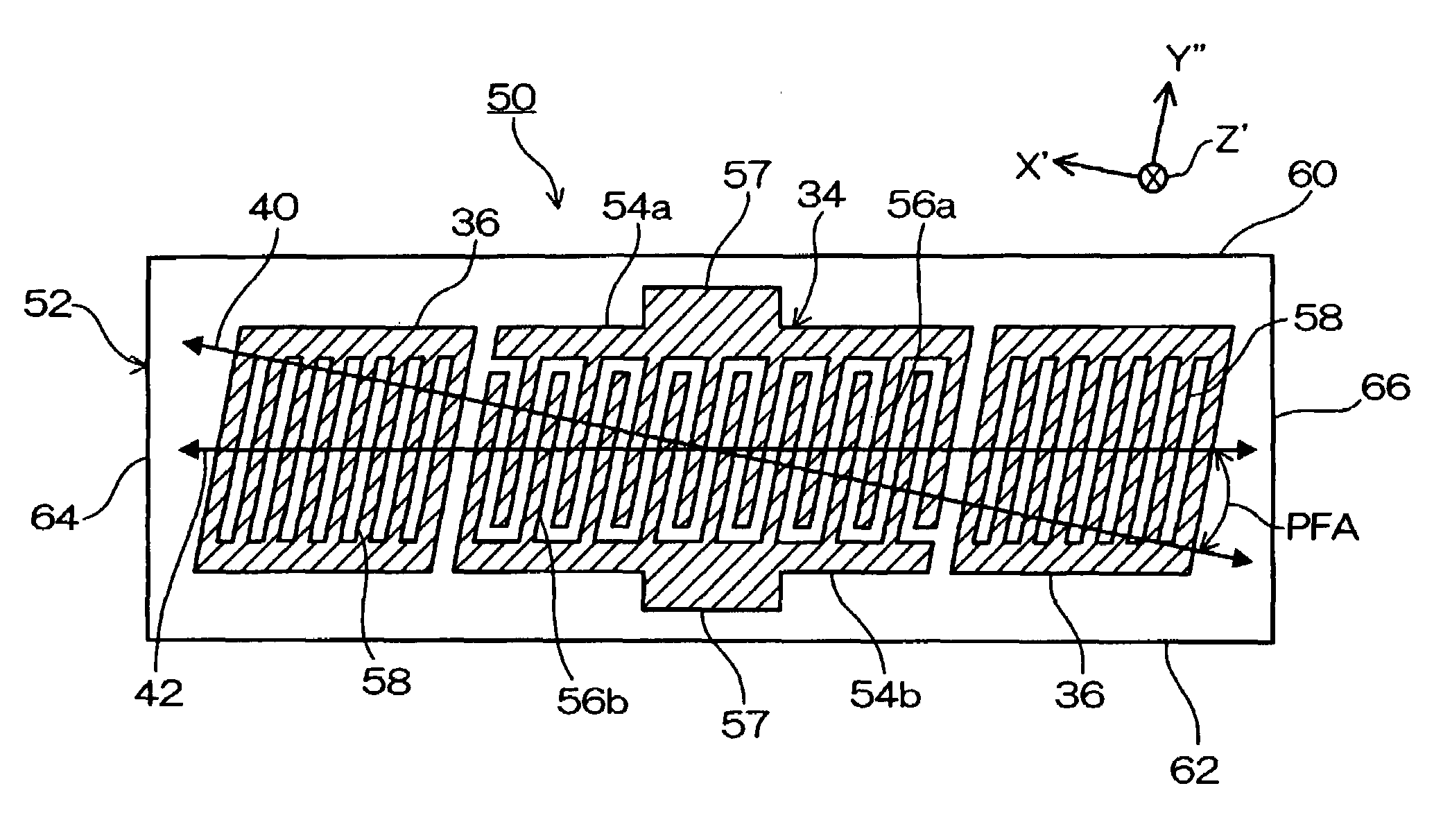
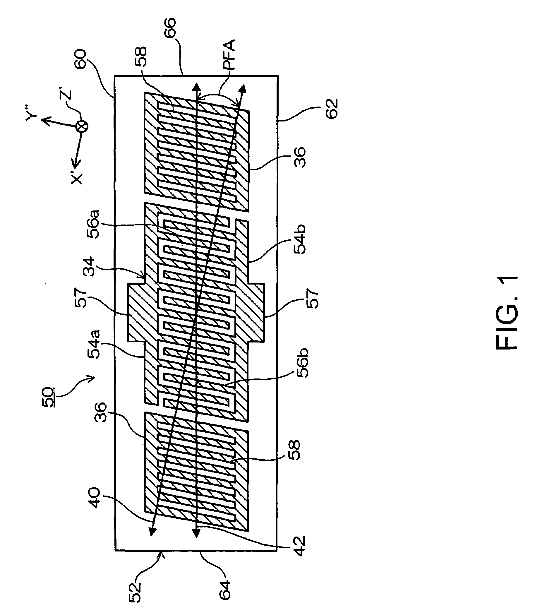
[0044]FIG. 1 is a plain view of the surface acoustic wave element according to the present invention. In FIG. 1, a surface acoustic wave element 50 is made from a quartz element 52 that is a piezoelectric substance and formed as a rectangular like. An IDT 34 is formed on a center part of a surface of the quartz element 52. The IDT 34 is configured with a paired interdigital transducer 54 (54a and 54b) in which an electrode fingers 56 (56a and 56b) equivalent to the comb teeth of the paired interdigital transducer 54 are arranged alternately and parallel with an equal distance. In the IDT 34, a surface acoustic wave having a predetermined frequency is generated in a surface layer part of a quartz plate 52 by a signal voltage applied between an interdigital transducer 54a and an interdigital transducer 54b. Also, each of the paired interdigital transducer 54 includes wire-bonding pad 57 at an outside center part thereof opposite from the electrode fingers 56.

[0045]Further, the surface...

third embodiment

[0075]In the surface acoustic wave element 50b of the third embodiment, the sides of the reflector 36 are extended to the edges of 64a and 66a, the sides being opposite from the IDT 34 side. The surface acoustic wave element 50b can reduce its length further shorter. This makes it possible to achieve the downsizing for further increasing the yield per quartz wafer. In addition, the edges 64a and 66a may be perpendicular to the direction 40 of the phase velocity of the surface acoustic wave element.

INDUSTRIAL APPLICABILITY

[0076]The surface acoustic wave elements 50, 50a, and 50b of each above-mentioned embodiment can be used for surface acoustic wave devices such like SAW resonators or SAW filters or the like.


PUM


Abstract

A surface acoustic wave element is provided including an IDT and reflectors provided on both sides of the IDT that are on a surface of a quartz plate. The quartz plate is made from an in-plane rotated ST cut quartz plate whose cutting angle is expressed as (0°, 113°-135°, ±(40°-49°)) by defining and using Euler angle. The IDT and reflectors are arranged at a slant of PFA±3° with respect to a direction of a phase velocity of a surface acoustic wave in the quartz plate. If the cutting angle of the quartz plate is expressed by the Euler angle (φ°, θ°, Ψ°), the power flow angle PFA is expressed that the PFA=0.374 (θ°−90°)−10.0°.

Description

RELATED APPLICATIONS[0001]This application claims priority to Japanese Patent Application Nos. 2003-414210 filed Dec. 12, 2003, 2004-242806 filed Aug. 23, 2004, and 2003-423153 filed Dec. 19, 2003 which are hereby expressly incorporated by reference herein in their entirety.BACKGROUND[0002]1. Technical Field[0003]The present invention relates to a surface acoustic wave element utilizing a surface acoustic wave and especially, a surface acoustic wave element in which a phase velocity and a group velocity of the surface acoustic wave are different in directions, and a method of manufacturing the same.[0004]2. Related Art[0005]A surface acoustic wave device (SAW device) utilizing a surface acoustic wave (SAW) uses a surface acoustic wave element in which an interdigital transducer (IDT) is formed on a surface of a piezoelectric plate such like quartz. Conventionally, the SAW devices have been widely used for high frequency filters because their characteristics in high frequency region ...

Claims


Application Information

Patent Timeline
Patent Type & Authority Patents(United States)
IPC IPC(8): H01L41/08H03H9/25H03H3/08H03H9/02H03H9/145
CPCH03H3/08H03H9/02551H03H9/14594H03H9/14547
Inventor YAMAZAKI, TAKASHIIIZAWA, KEIGO
Owner SEIKO EPSON CORP
Why Eureka
Try Eureka