Vehicle exhaust heat recovery system

a vehicle exhaust and heat recovery technology, applied in the direction of machines/engines, machine operation modes, lighting and heating apparatus, etc., can solve the problems of low energy conversion efficiency, driving the turbine by means of the coolant water of the internal combustion engine, and vehicle exhaust heat recovery systems, etc., to achieve excellent energy conversion efficiency and small size

Inactive Publication Date: 2008-04-08
TOYOTA IND CORP
View PDF12 Cites 15 Cited by
  • Summary
  • Abstract
  • Description
  • Claims
  • Application Information

AI Technical Summary

Benefits of technology

[0004]An object of the invention is to provide a vehicle exhaust heat recovery system that has a small size and excellent energy conversion efficiency.
[0008]In one embodiment, the generator is operatively connected to the above described expander. The generator is driven by the motive power generated at the expander to generate electric power. Accordingly, the electric power that is supplied by the drive source in the conventional vehicle can be compensated by the electric power generated by the expander to reduce the load for generating electricity at the drive source.
[0009]In a further embodiment, the generator is also operatively connected to the vehicle drive source. Accordingly, in the case where the amount of the vehicle exhaust heat is small and the expander is unable to generate efficient motive power, the generator can be driven by the motive power supplied by the drive source to secure necessary electric power for the vehicle. In the case where the motive power generated by the expander exceeds in amount from that necessary for driving of the generator, a motive power in excess of that for the operation of the generator is generated by the expander. If the excess motive power is transmitted to the drive source, the driving of the vehicle can be facilitated so that the load of the drive source can further be reduced.
[0010]In a further embodiment of the invention, the refrigerant expanded at the expander is sent back to the refrigeration circuit by way of the inside of the generator. Accordingly, the inside of the generator is cooled by the refrigerant which has comparatively low temperature after expansion at the expander to improve electric power generation of the generator.

Problems solved by technology

However, the known structure for driving the turbine by means of the coolant water of the internal combustion engine has low energy conversion efficiency from thermal energy (exhaust heat from the engine) to mechanical energy (motive power generated by the turbine) since the expansion ratio of the coolant water is high.
This causes a problem of a vehicle exhaust heat recovery system that is large in size and which is difficult to be installed into the vehicle.

Method used


Image

  • Vehicle exhaust heat recovery system
  • Vehicle exhaust heat recovery system
  • Vehicle exhaust heat recovery system

Examples


Embodiment Construction

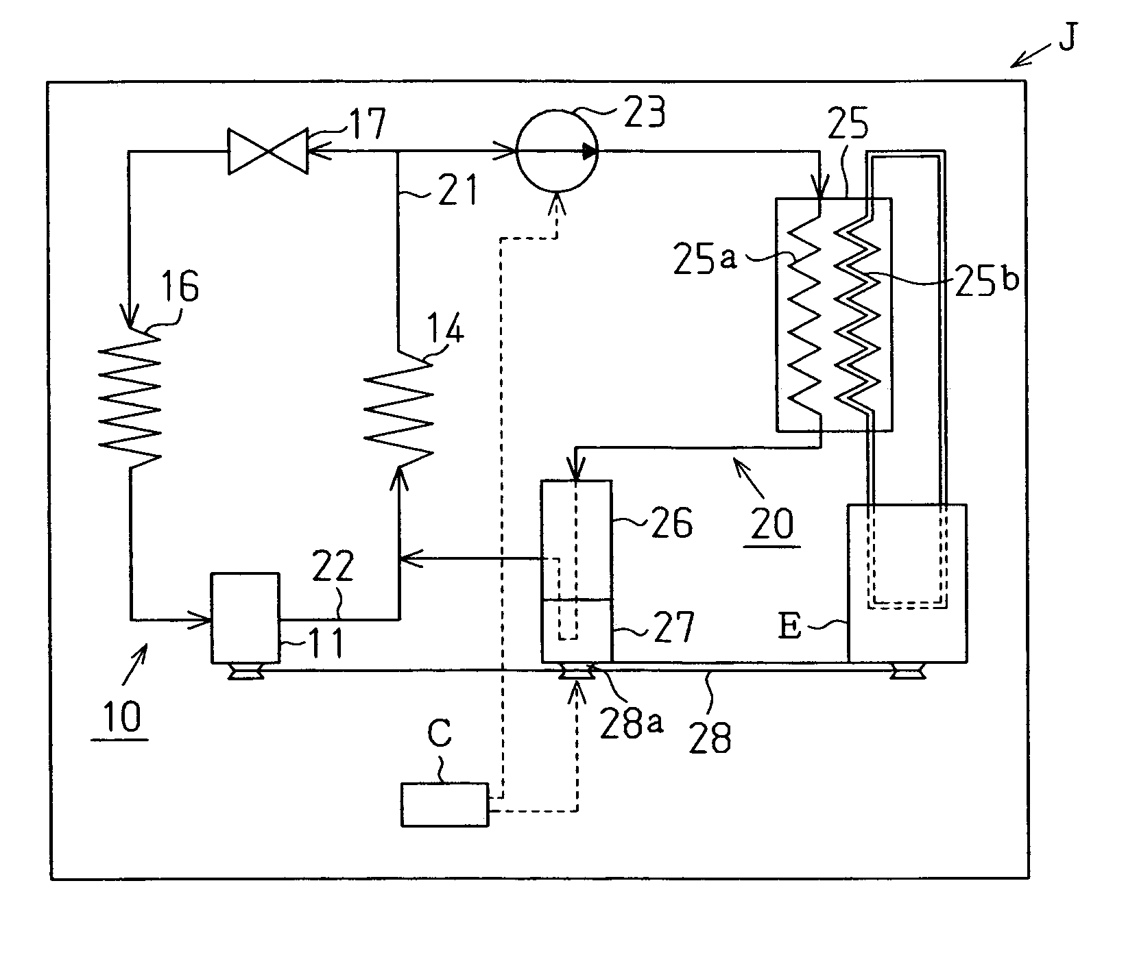
[0016]An embodiment of the vehicle exhaust heat recovery system of the present invention is described below.

[0017]Referring to FIG. 1, an air conditioning system provided in a vehicle J includes a refrigeration circuit 10 of a vapor compression type. As the refrigerant of the refrigeration circuit 10, for example, Freon or carbon hydride can be used. The refrigeration circuit 10 comprises a cooler 14, an expansion valve 17 and an evaporator 16. The compressor 11 is driven by an internal combustion engine (hereinafter referred to as an “engine”) E that is provided as a drive source for the vehicle J, and performs compression of the refrigerant gas. The refrigerant gas discharged from the compressor 11 and having high temperature and high pressure is cooled by the cooler 14. The refrigerant from the cooler 14 is decompressed by the expansion valve 17 which functions as a decompression device. The refrigerant from the expansion valve 17 is heated by the evaporator 16. The refrigerant, ...


PUM


Abstract

A vehicle exhaust heat recovery system includes a vapor compression type refrigeration circuit, a boiler to which the refrigerant is introduced from the refrigeration circuit and heated, and an expander for generating motive power by expanding the heated refrigerant. The refrigerant circulates in the refrigeration circuit. The boiler heats the refrigerant introduced therein using exhaust heat generated by the vehicle. The refrigerant that has been subjected to expansion is recycled to the refrigeration circuit.

Description

BACKGROUND OF THE INVENTION[0001]The present invention relates to a heat recovery system, in particular, a vehicle heat recovery system which generates motive energy by recovering exhaust heat from a combustion engine, which is a drive source of the vehicle.[0002]A known vehicle exhaust heat recovery system generates motive power by driving a turbine using coolant water (high temperature vapor) that has been heated by the heat generated by an internal combustion engine. The motive force drives a generator that is operatively connected to the turbine for generating electric power (see for example Japanese Laid-Open Patent Publication 2000-345915).[0003]However, the known structure for driving the turbine by means of the coolant water of the internal combustion engine has low energy conversion efficiency from thermal energy (exhaust heat from the engine) to mechanical energy (motive power generated by the turbine) since the expansion ratio of the coolant water is high. In order to imp...

Claims


Application Information

Patent Timeline
Patent Type & Authority Patents(United States)
IPC IPC(8): F25B1/00F01K23/02B60H1/00B60H1/02B60H1/32F01P3/20F02B75/04F02G5/00F02G5/02F02G5/04F25B27/02
CPCB60H1/00878B60H1/02B60H1/3213F02B75/04B60H2001/3288F25B27/02F25B2400/141Y02E20/14Y02A30/274
Inventor WANG, XIAOLIANGMOROI, TAKAHIROSONOBE, MASANORIKAWAGUCHI, MASAHIRO
Owner TOYOTA IND CORP
Why Eureka
Try Eureka