Compression ratio variable device of internal combustion engine

a compression ratio and variable technology, applied in the direction of engines, machines/engines, engine controllers, etc., can solve the problems of increasing the overall cost, difficulty in increasing the compression ratio of the engine at the high compression ratio position, etc., and achieve the effect of simplifying the arrangement of driving means

Inactive Publication Date: 2008-04-08
HONDA MOTOR CO LTD
View PDF8 Cites 6 Cited by
  • Summary
  • Abstract
  • Description
  • Claims
  • Application Information

AI Technical Summary

Benefits of technology

[0004]The present invention has been accomplished under the above-mentioned circumstances, and it is an object thereof to provide an internal combustion engine variable compression ratio system that enables a piston outer to be moved to a low compression ratio position and a high compression ratio position simply and reliably without rotating the piston outer.
[0009]Moreover, as described above, when the piston outer has reached the high compression ratio position, since relative axial movement of the piston inner and the piston outer is prevented by operation of the piston outer high compression ratio position latching means, when the piston outer low compression ratio position latching means is released and the piston outer is moved from the low compression ratio position to the high compression ratio position by virtue of a spontaneous external force, even if there is a delay in movement of the raising member to the raised position and the piston outer receives a kick from the piston outer stopper means, the kick is borne by the piston outer high compression ratio position latching means, thus preventing the piston outer from bouncing back from the high compression ratio position and thereby reliably holding the piston outer at the high compression ratio position.
[0010]Since the piston outer does not rotate relative to the piston inner, it can move between the low compression ratio position and the high compression ratio position, and the shape of the top face of the piston outer, which faces the combustion chamber, can match the shape of the combustion chamber, thereby increasing effectively the compression ratio when the piston outer is at the high compression ratio position. Moreover, regardless of whether the piston outer is at the low compression ratio position or the high compression ratio position, during the expansion stroke of the engine, a large thrust that the piston outer receives from the combustion chamber is received by the raising member. In this way, the thrust is prevented from acting on the actuator, and it is therefore possible to reduce the capacity of the actuator and consequently the dimensions thereof. When the actuator is of a hydraulic type, since the thrust does not act thereon, a high pressure seal is not needed, and even if some bubbles form in a hydraulic chamber, the high compression ratio position of the piston outer will not become unstable.
[0012]In accordance with the second aspect, the first and second latching members, which are both supported by the piston inner, enable the piston outer to be held at the low compression ratio position or at the high compression ratio position, thereby contributing to a simplification of the arrangement of the piston outer low compression ratio position latching means and the piston outer high compression ratio position latching means.
[0016]In accordance with the fourth aspect, simply controlling the supply and release of hydraulic pressure to and from the hydraulic piston in cooperation with the operating spring enables the first and second arms to be operated alternately, thus simplifying the arrangement of the driving means.

Problems solved by technology

However, in the above-mentioned system (1), since it is necessary to rotate the piston outer in order to move it to the low compression ratio position and the high compression ratio position, the shape of the top face of the piston outer cannot be set freely so as to match the shape of the roof of a combustion chamber and the positional arrangement of intake and exhaust valves, and it is difficult to increase the compression ratio of the engine sufficiently at the high compression ratio position.
Furthermore, in the above-mentioned system (2), particularly when the piston outer is at the high compression ratio position, since a large thrust load imposed on the piston outer during an expansion stroke of the engine is borne by the hydraulic pressure of the upper hydraulic chamber, it is necessary for the upper hydraulic chamber to have a seal that can withstand high pressure and, moreover, if bubbles are generated in the upper hydraulic chamber, since the high compression ratio position of the piston outer becomes unstable, it is necessary to provide means for removing such bubbles, thus inevitably increasing the overall cost.

Method used


Image

  • Compression ratio variable device of internal combustion engine
  • Compression ratio variable device of internal combustion engine
  • Compression ratio variable device of internal combustion engine

Examples


first embodiment

[0031]the present invention is now explained with reference to FIG. 1 to FIG. 12.

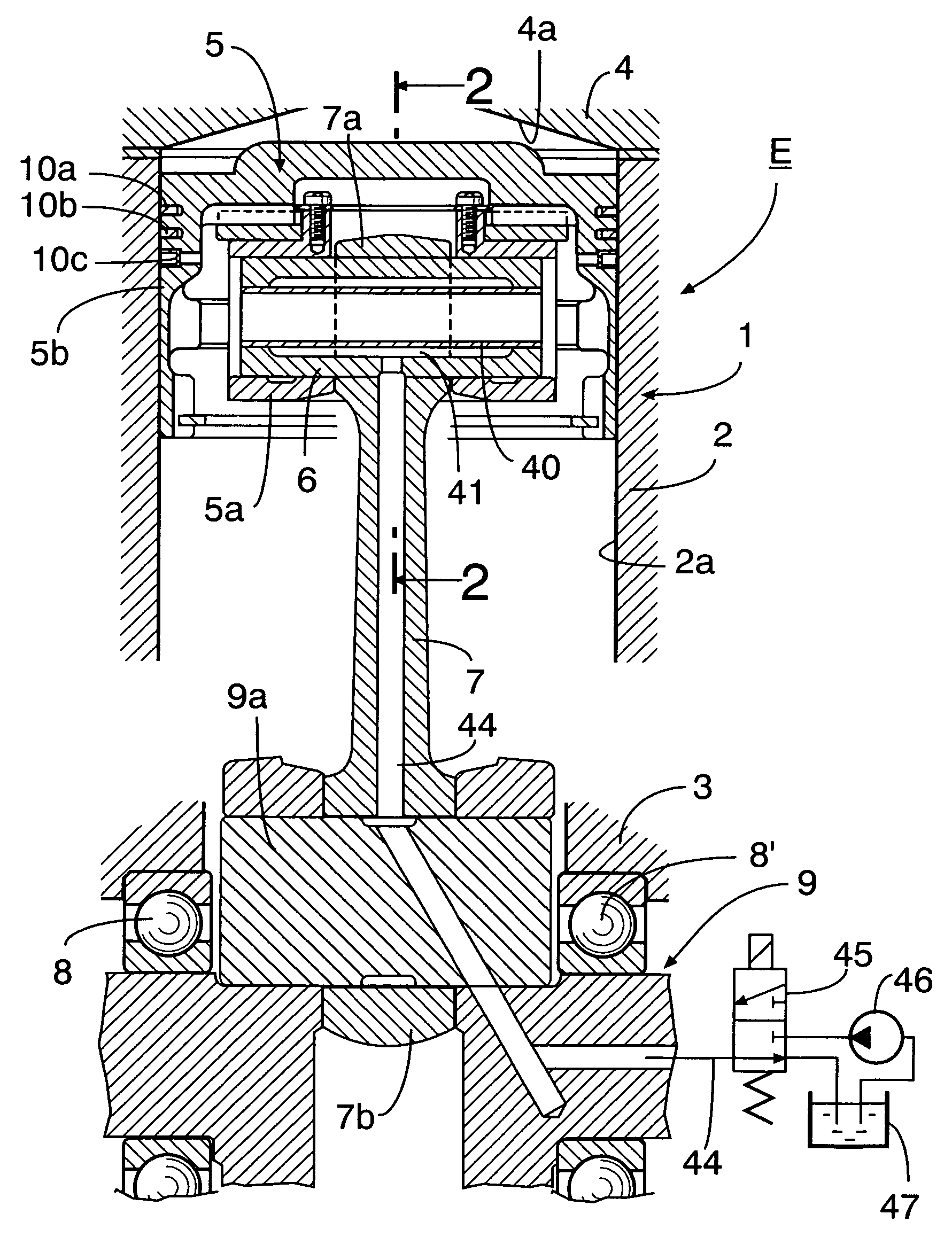
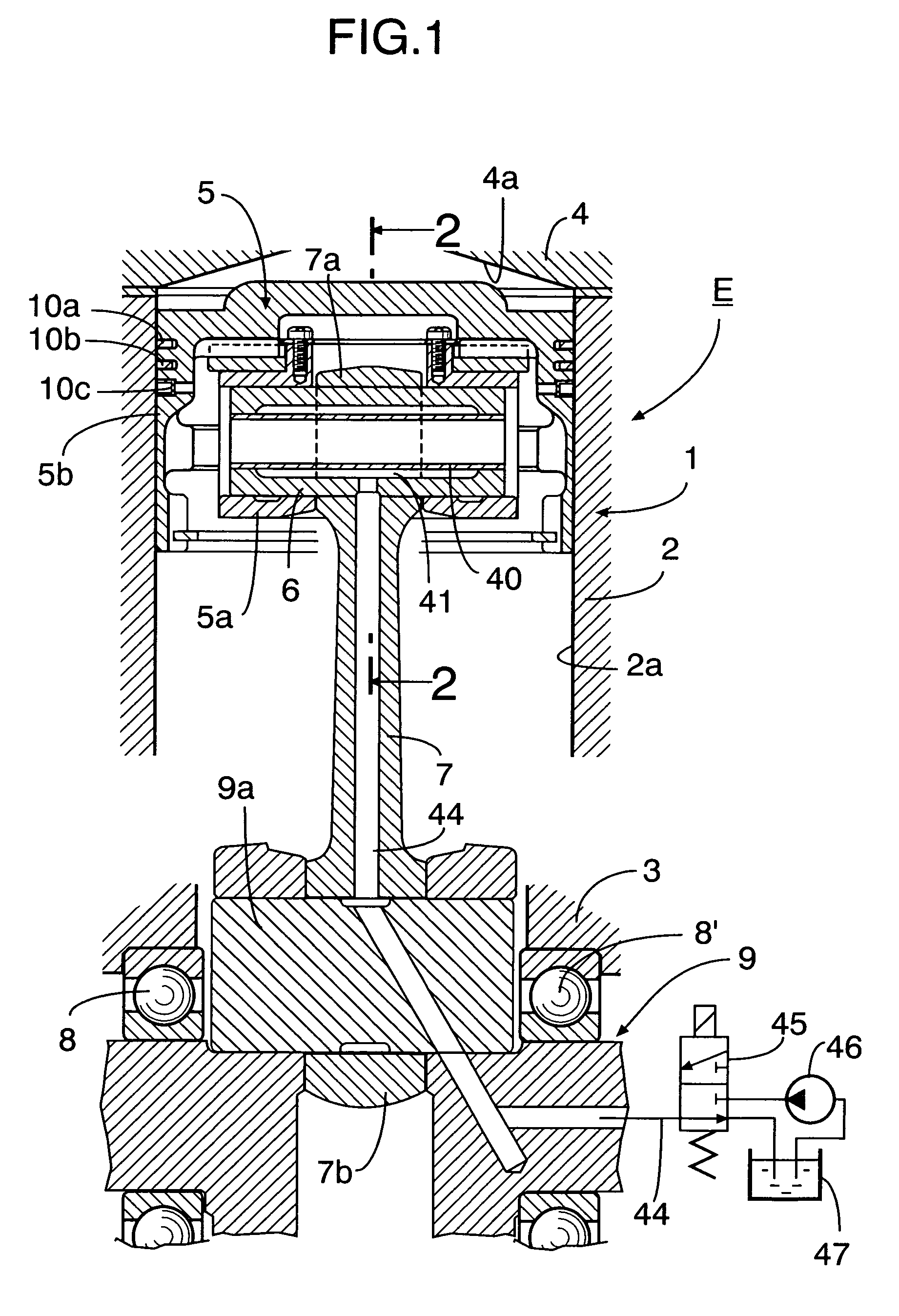
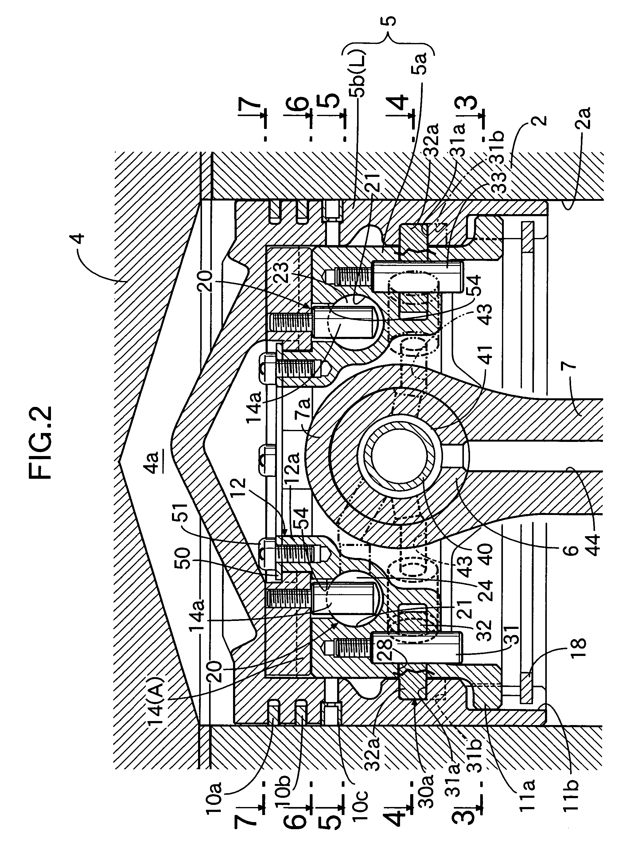
[0032]In FIG. 1 and FIG. 2, an engine main body 1 of an internal combustion engine E includes a cylinder block 2 having a cylinder bore 2a, a crankcase 3 joined to the lower end of the cylinder block 2, and a cylinder head 4 joined to the upper end of the cylinder block 2 and having a combustion chamber 4a extending from the cylinder bore 2a. A piston 5 is fitted slidably in the cylinder bore 2a, a little end 7a of a connecting rod 7 is connected to the piston 5 via a piston pin 6, and a big end 7b of the connecting rod 7 is connected via a pair of left and right bearings 8 and 8′ to a crankpin 9a of a crankshaft 9 rotatably supported in the crankcase 3.

[0033]The piston 5 includes a piston inner 5a and a piston outer 5b, the piston inner 5a being connected to the little end 7a of the connecting rod 7 via the piston pin 6, and the piston outer 5b, whose top face faces the combustion chamber 4a, being sli...

second embodiment

[0072]the present invention is now explained with reference to FIG. 13A to FIG. 13C.

[0073]The second embodiment has the same arrangement as that of the preceding embodiment except that a first cam 116 and a second cam 117 formed on a raising member 114 and a piston outer 105b respectively are provided with inclined faces 116a and 117a which slide away from each other in the axial direction when a raising member 114 pivots from a non-raised position A to a raised position B, and in FIG. 13A to FIG. 13C parts corresponding to the parts of the preceding embodiment are denoted by reference numerals and symbols that are obtained by adding 100 to the corresponding reference numerals and symbols of the preceding embodiment, thereby avoiding duplication of the explanation.

[0074]In the second embodiment, since one side of each of the cams 116 and 117 is the inclined face 116a or 117a, compared with the preceding embodiment, the gap between adjacent cams 116 and adjacent cams 117 is widened, ...


PUM


Abstract

An internal combustion engine variable compression ratio system is provided that includes a piston inner (5a), a piston outer (5b) that is fitted around the outer periphery of the piston inner (5a) so that it can slide only in the axial direction and is capable of moving between a low compression ratio position (L) and a high compression ratio position (H), a raising member (14) that can pivot around axes of the piston inner and outer (5a, 5b) between a non-raised position (A) and a raised position (B), and an actuator (20) connected to the member (14) and pivoting it to the non-raised position (A) or the raised position (B), in which piston outer high compression ratio position latching means (30b) is disposed between the piston inner (5a) and the piston outer (5b) and operates, when the piston outer (5b) has reached the high compression ratio position (H), so as to prevent relative axial movement of the piston inner (5a) and the piston outer (5b). It is thereby possible to provide a variable compression ratio system that enables the piston outer to be moved to the low compression ratio position and the high compression ratio position simply and reliably without rotating the piston outer.

Description

FIELD OF THE INVENTION[0001]The present invention relates to an internal combustion engine variable compression ratio system and, in particular, to an improvement thereof in which a piston includes a piston inner and a piston outer, the piston inner being connected to a connecting rod via a piston pin, and the piston outer, while being connected to the piston inner so as to have an outer end face thereof facing a combustion chamber, being capable of moving between a low compression ratio position close to the piston inner and a high compression ratio position close to the combustion chamber, the compression ratio of the engine being decreased by moving the piston outer to the low compression ratio position, and the compression ratio being increased by moving the piston outer to the high compression ratio position.BACKGROUND ART[0002]Conventionally, with regard to such an internal combustion engine variable compression ratio system, there is a known system (1) in which a piston outer...

Claims


Application Information

Patent Timeline
Patent Type & Authority Patents(United States)
IPC IPC(8): F02D15/02F02B75/04F02F3/00
CPCF02B75/044F02D15/04
Inventor KONDO, TAKASHIHIRANO, MAKOTO
Owner HONDA MOTOR CO LTD
Why Eureka
Try Eureka