Fuel injector with pressure balancing valve

a fuel injector and pressure balancing valve technology, applied in the field of piezoelectric fuel injectors, can solve problems such as disadvantages of conventional piezoelectric fuel injectors, and achieve the effect of improving fuel economy and reducing exhaust emissions

Inactive Publication Date: 2008-04-08
CUMMINS INC
View PDF14 Cites 20 Cited by
  • Summary
  • Abstract
  • Description
  • Claims
  • Application Information

AI Technical Summary

Benefits of technology

[0012]In view of the foregoing, the present invention provides a fuel injection system to aid in reducing exhaust emissions and improving fuel economy, especially in engines not using exhaust gas recirculation.
[0014]Accordingly, the present invention is directed to a fuel injector with a actuator, such as a piezoelectric actuator, whose operation is independent of injection pressure in order to permit the actuator to operate more effectively and efficiently with extremely high injection pressures. Furthermore, the present invention is directed to a fuel injector that overcomes thermal effects which negatively impact the dimensional characteristics and performance of conventional piezoelectric fuel injectors.
[0015]Because the actuator operates independently of injection pressure, it does not have to supply such high forces. In particular, for a fuel injector using a piezoelectric actuator, a smaller, less expensive, high volume piezo stack can be used. For instance, where a 8000 N piezo stack is required by a conventional piezoelectric fuel injector, a 500 N stack is adequate for the present invention employing the same high pressure. Thus, the fuel injector according to the present invention can use a piezoelectric actuator that is smaller than conventional piezoelectric actuators. Also, the power required for the smaller piezoelectric actuator in the present invention is less than the power needed to operate the convention devices. Moreover, with a smaller piezoelectric actuator, the present invention can be more compact for better packaging in the engine.
[0016]An exemplary embodiment of the present invention employs a pressure balanced control valve. Because the valve is pressure balanced, there is no need for greater piezo forces with the use of greater injection pressures, as conventionally required. The embodiment also employs a hydraulic linkage, or column, to connect the piezoelectric actuator and the control valve. As a result, the length of the hydraulic linkage compensates for thermal growth and part tolerances, allowing the actuator performance to be independent of temperature. Accordingly, the piezoelectric actuator of this exemplary embodiment functions independently of injection pressure and temperature variation and provides a cost effective way to control fuel injection, which improves fuel economy and reduces exhaust emissions.

Problems solved by technology

As noted previously, however, there are disadvantages to conventional piezoelectric fuel injectors, especially when operating with such high pressures.

Method used


Image

  • Fuel injector with pressure balancing valve
  • Fuel injector with pressure balancing valve
  • Fuel injector with pressure balancing valve

Examples


Embodiment Construction

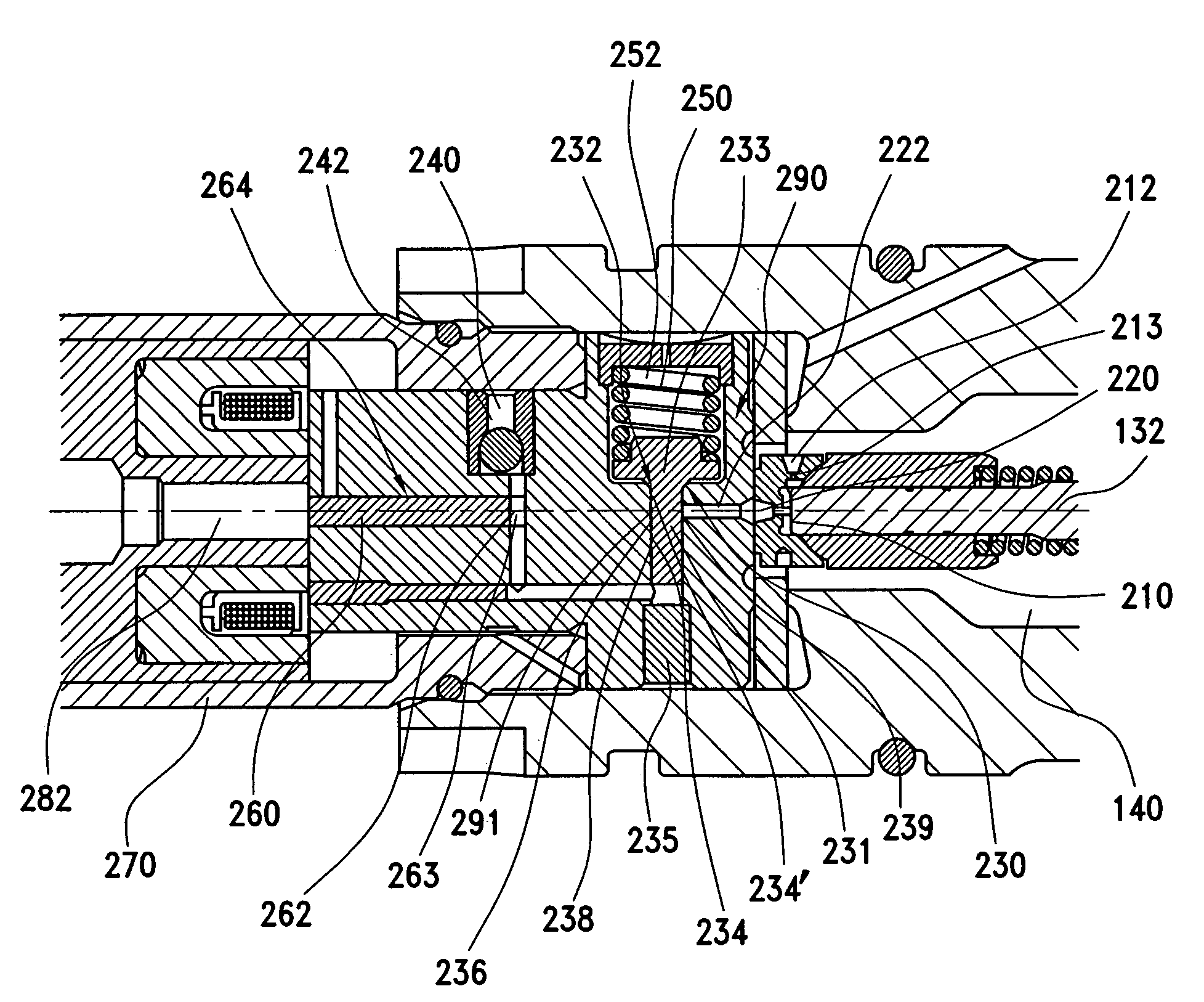
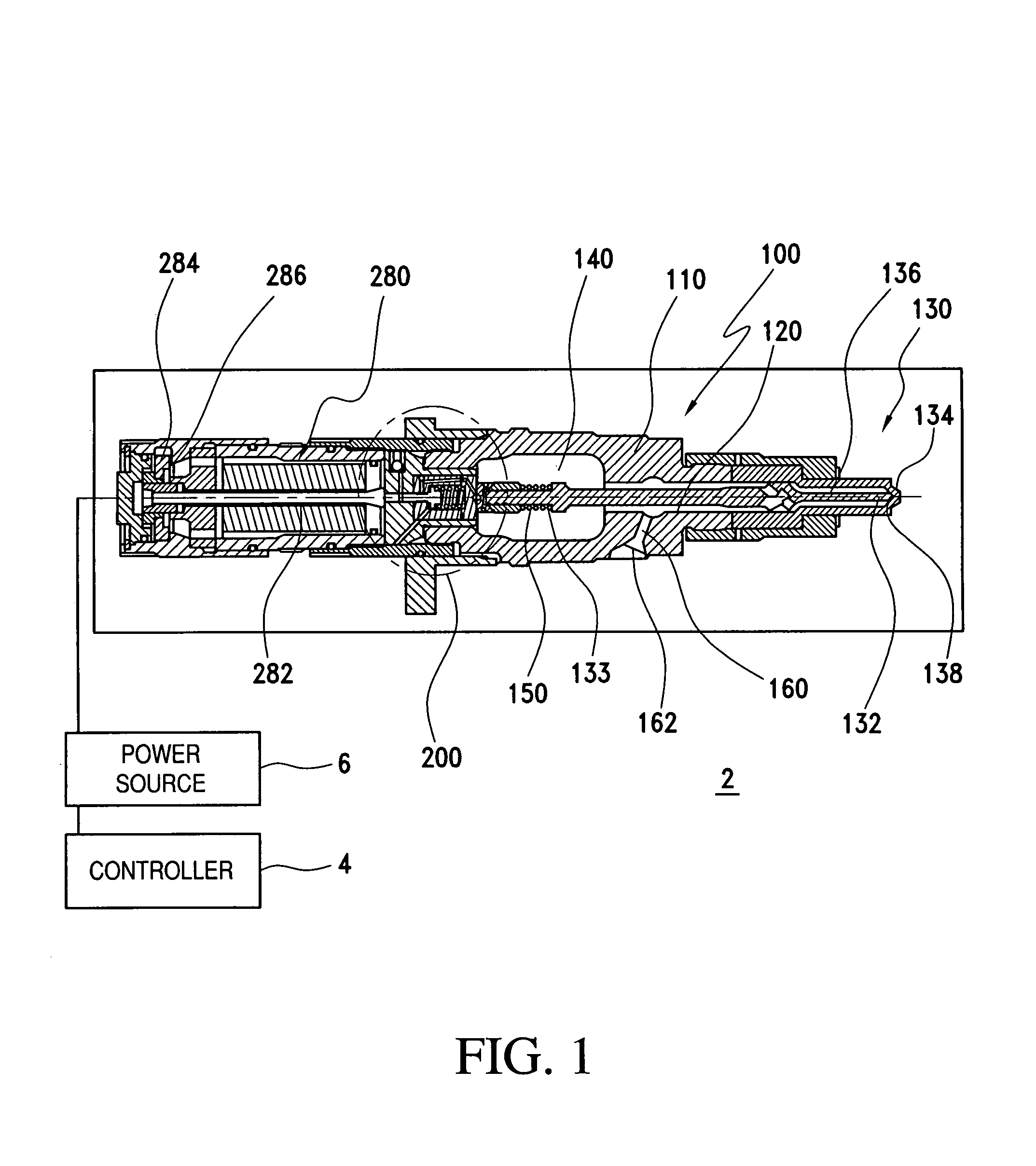
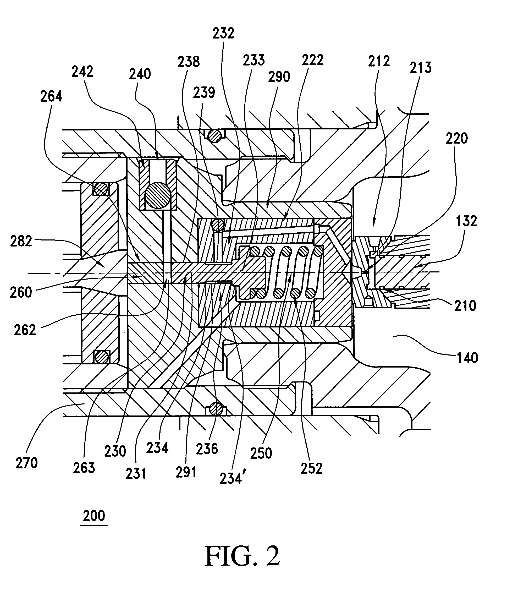
[0023]FIG. 1 shows a schematic illustration of a piezoelectric fuel injection system 2 in accordance with one embodiment of the present invention that avoids the above noted limitations of conventional fuel injection systems. As described in further detail below, the piezoelectric fuel injection system 2 enables fuel injection in an internal combustion engine, such as a diesel engine, where actuation operates independently of injection pressure and operating temperature. Of course, the present invention may also be applied to other types of internal combustions as well.

[0024]The piezoelectric fuel injection system 2 of the illustrated embodiment includes a controller 4, such as an electronic control unit, that is connected to a power source 6, the controller 4 being adapted to control the power source 6. The power source 6 of the piezoelectric fuel injection system 2 is connected to a fuel injector 100 and provides power thereto, in the manner as further described below in accordanc...


PUM


Abstract

A fuel injector device, for injecting fuel into a combustion chamber of an internal combustion engine, has a nozzle valve and nozzle valve control assembly adapted to use a control valve and high pressure fuel in the fuel injector in order to actuate movement of the nozzle valve between an open position to inject fuel and a closed position to terminate fuel injection. The nozzle valve control assembly employs a pressure balancing control valve so that the fuel pressure exerts a zero net force on the control valve in a dimension along which the control valve moves. Thus, the actuation occurs independently of the fuel pressure. In addition, the actuator is operably connected to the control valve by at least a hydraulic linkage, where the hydraulic linkage compensates for changes in the actuator and the injector body due to changes in temperature.

Description

BACKGROUND OF THE INVENTION[0001]1. Field of the Invention[0002]The present invention is directed to fuel injection systems, and more particularly to piezoelectric injection systems that function independently of injector pressure and operating temperature.[0003]2. Description of Related Art[0004]In most fuel supply systems applicable to internal combustion engines, fuel injectors are used to inject fuel pulses into the engine combustion chamber. A commonly used injector is a closed-nozzle injector which includes a nozzle assembly having a spring-biased nozzle valve element positioned adjacent the nozzle orifice for allowing fuel to be injected into the cylinder. The nozzle valve element also functions to provide a deliberate, abrupt end to fuel injection, thereby preventing a secondary injection which causes unburned hydrocarbons in the exhaust. The nozzle valve is positioned in a nozzle cavity and biased by a nozzle spring so that when an actuated force exceeds the biasing force o...

Claims


Application Information

Patent Timeline
Patent Type & Authority Patents(United States)
IPC IPC(8): F02M37/04F02M37/08
CPCF02M47/027F02M51/0603F02M61/167F02M63/0026F02M63/004F02M63/0073F02M2200/706
Inventor GANT, GARY L.
Owner CUMMINS INC
Why Eureka
Try Eureka