Reactive load resonant drive circuit

a reactive load and drive circuit technology, applied in the direction of valves, generators/motors, mechanical equipment, etc., can solve the problems of unfavorable lower limit of flow path open time, slow charge transfer speed, and inconvenient operation of mass flow controller devices. achieve rapid charge transfer, avoid excessive peak current and significant resistive energy dissipation, the effect of rapid charge transfer

Inactive Publication Date: 2008-04-08
HITACHI METALS LTD
View PDF15 Cites 2 Cited by
  • Summary
  • Abstract
  • Description
  • Claims
  • Application Information

AI Technical Summary

Benefits of technology

[0010]This invention provides energy efficient circuitry for rapid transfer of charge to and from a reactive load. The invention generally comprises a resonant drive circuit for rapidly transferring charge to a reactive load while avoiding excessive peak currents and significant resistive energy dissipation. The invention also features circuitry for recovering a substantial portion of the energy delivered to the reactive load while still permitting rapid cycling of the load drive circuit.
[0011]In one embodiment of the invention, a resonant drive circuit comprises a piezoelectric actuator and a series inductive element for rapid delivery of charge from a voltage source to the capacitive actuator load. A semiconductor switch controls the application of voltage to the circuit from a voltage source, and a series diode rectifies the resonant current waveform of the circuit for positive charge transfer to the actuator. The resonant drive circuit is optimized for rapid transfer of charge from the voltage source to the piezoelectric actuator with minimal peak currents. The switched circuit arrangement also allows the piezoelectric actuator to be driven affirmatively to a known voltage reference while naturally locating and managing zero-voltage crossings within the circuit for effective charging and discharging of the actuator device.
[0012]In one embodiment of the invention, an energy conserving discharge circuit is provided in addition to a resonant drive circuit. A semiconductor switch creates a single-stage resonant discharge path from the piezoelectric actuator through the inductive element of a resonant drive circuit. The discharge circuit further comprises nonlinear elements to ensure rapid and positive transfer of charge from the actuator. Energy recovered by the discharge circuit is returned to the power source of the actuator drive circuit. The resonant discharge circuit is optimized so as to recover and recycle a substantial portion of the energy delivered to the reactive load without unduly limiting the cycling frequency of the load drive circuit.
[0013]The invention provides for increased speed and energy efficiency of circuitry used to control operation of reactive loads. For example, the circuitry of the invention permits the speed at which a piezoelectric linear actuator can operate a mechanical valve to be increased several fold while significantly reducing electrical input power and power dissipation requirements. Proper selection of the resonant elements of the drive circuit ensures that charge is transferred to the reactive load within actuation time limits and peak current limits of the circuit. Transferring an electrical charge using resonant drive circuitry of the invention provides for nearly all of the source energy to be delivered to the reactive load, allowing for further reductions in electrical power requirements.
[0014]In a further embodiment of the invention, the activation period of a semiconductor switch controls the actuation increment of a piezoelectric device or other reactive load. A resonant drive circuit comprises a piezoelectric actuator and a series inductive element together with nonlinear devices that ensure rapid and positive delivery of charge from a voltage source to the actuator load. Control of the activation (“on”) time of the semiconductor switch results in a variable quantity of electrical charge delivered through the resonant circuit, thus providing for incremental actuation of the piezoelectric load.

Problems solved by technology

The speed of charge transfer is limited, however, by peak current stresses placed on the internal bond wires connecting the drive circuit to the piezoelectric actuator, as well as by practical considerations of the cost, size, and electrical isolation of high-current switches and other components.
As a result, contemporary mass flow controller devices tend to have relatively slow actuation times on the order of several hundred milliseconds.
For many process applications, these actuation times impose an undesirable lower limit on the open time of the flow path, or upper limit on the repetition rate at which the controller may be operated.
The amount of electrical power consumed and dissipated by a mass flow controller may also limit its suitability for many process applications.
Moreover, the energy used to charge the piezoelectric actuator is typically not recovered, thus requiring dissipation of that stored energy when the actuator is discharged.
As a result, power consumption and dissipation needs of a high-speed mass flow controller may become unacceptably high in a system environment where power and heat sinking resources are allocated sparingly.
In addition to the added cost and complexity of this approach, however, a significant disadvantage is that the vented material often cannot be recovered due to contamination concerns.
For many processes, particular in the manufacture of semiconductor devices, this can result in significant waste of expensive feed gas materials along with an attendant need for scrubbing or abating greater quantities of the gases downstream of the process.

Method used


Image

  • Reactive load resonant drive circuit
  • Reactive load resonant drive circuit
  • Reactive load resonant drive circuit

Examples


Embodiment Construction

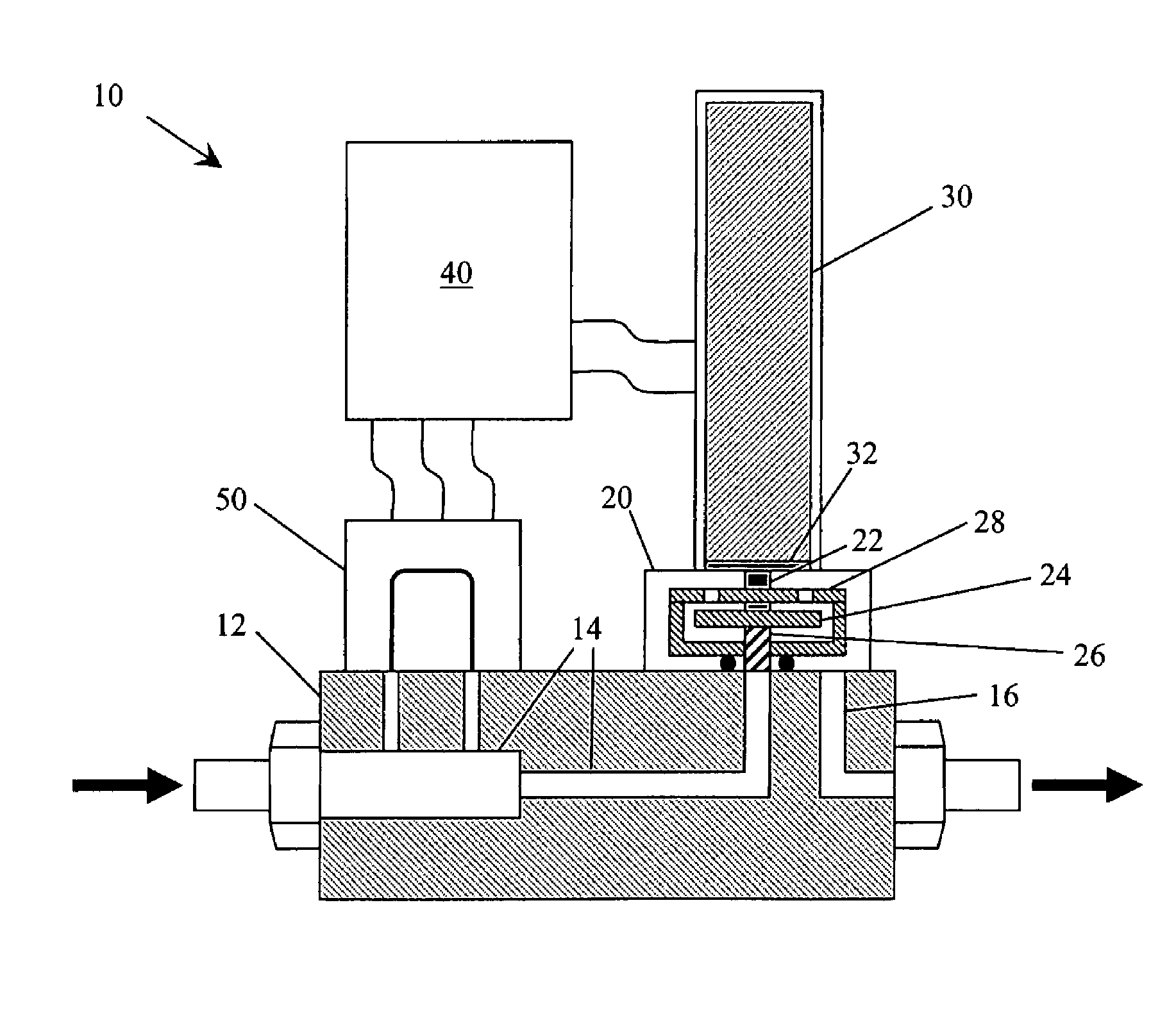
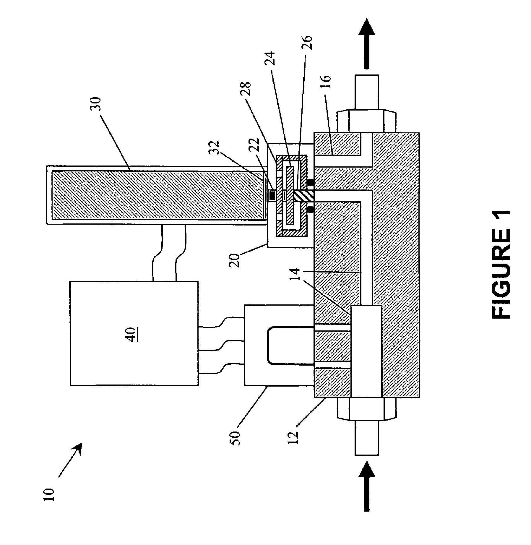
[0020]FIG. 1 illustrates one embodiment of a mass flow controller device that incorporates features of the invention. Mass flow controller 10 comprises controller base 12 having upstream and downstream gas flow passages 14 and 16, respectively. Gas flow between passages 14 and 16 is controlled by valve assembly 20. When actuated, piezoelectric stack 30 transmits force through diaphragm 32 and plunger 22 to poppet 24, which opposes the force of spring 26 to create a gas flow path through orifice plate 28. Actuation of piezoelectric stack 30 is controlled by drive circuitry on electronics board 40. A sensor loop 50 provides measurements of properties of the gas stream flow to control electronics on electronics board 40.

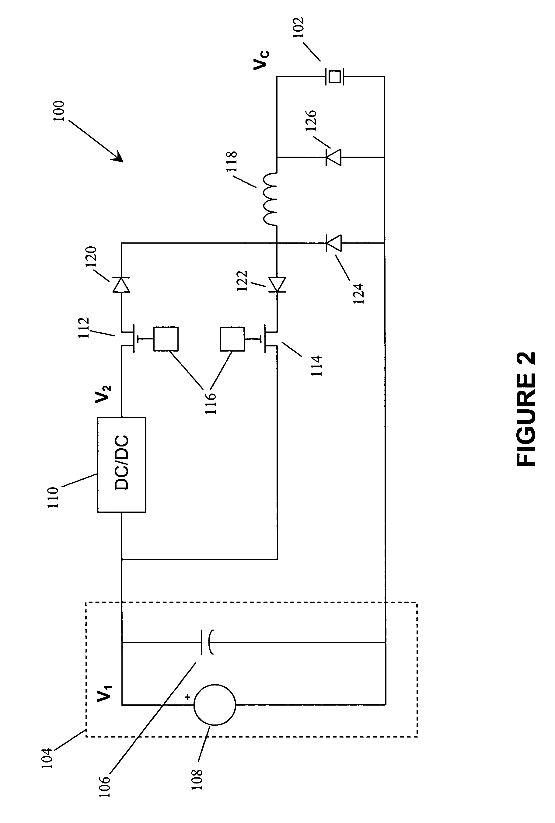
[0021]FIG. 2 illustrates actuation circuitry in accordance with one embodiment of the invention. Circuit 100 drives a piezoelectric actuator 102 depicted as a capacitive load. Circuit 100 further comprises low voltage source 104 providing DC power at voltage V1 and step...


PUM


Abstract

Energy efficient circuitry is provided for rapid transfer of charge to and from a reactive load while avoiding excessive peak currents and significant resistive energy dissipation. For example, circuitry of the invention provides for rapid actuation of a piezoelectric mass flow valve actuator while significantly reducing electrical input power and power dissipation requirements. The invention also features circuitry for recovering a substantial portion of the energy delivered to the reactive load while still permitting rapid cycling of the load drive circuit. Controlling the activation interval of the drive circuitry provides for incremental actuation or positioning of the reactive load.

Description

BACKGROUND OF THE INVENTION[0001]1. Field of the Invention[0002]This invention relates generally to electrical control of a reactive load, and more particularly to high speed, low loss control of a piezoelectric actuator or other electromechanical positioning device.[0003]2. Brief Description of the Prior Art[0004]A piezoelectric linear actuator is a nano-positioning device that deforms its shape in response to a stimulus of electrical charge. Piezoelectric actuators are used to operate mechanical valves that regulate the flow of materials in such diverse applications as automobile fuel injectors, hydraulic servovalves, and ink jet printer nozzles. Piezoelectric linear actuators are particularly well suited for use in mass flow controller products, such as those employed in connection with plasma processing equipment, because the actuators can be operated for billions of cycles with virtually no loss in performance. Compared to other electromechanical actuators such as solenoids or ...

Claims


Application Information

Patent Timeline
Patent Type & Authority Patents(United States)
IPC IPC(8): H01L41/08
CPCF16K31/004H01L41/042H10N30/802
Inventor FINLEY, KENNETH W.
Owner HITACHI METALS LTD
Why Eureka
Try Eureka