Method of catalytic decomposition of water

a catalytic decomposition and water technology, applied in the direction of metal/metal-oxide/metal-hydroxide catalysts, physical/chemical process catalysts, instruments, etc., can solve the problems of inability to achieve direct thermal decomposition of water to produce hydrogen, and poor decomposition reaction efficiency

Inactive Publication Date: 2008-04-15
HITACHI LTD
View PDF14 Cites 9 Cited by
  • Summary
  • Abstract
  • Description
  • Claims
  • Application Information

AI Technical Summary

Problems solved by technology

Accordingly, there is no solution to produce hydrogen by a pure thermal decomposition of water.
Therefore, a direct thermal decomposition of water to produce hydrogen is not practical.
Since the reaction proceeds backward if ΔG is positive, efficiency of decomposition reaction is bad and the reaction is unstable; thus the industrial production process will not be formulated.
The above mentioned patent documents do not disclose the formation of micro cells comprising a catalyst of a solid acid catalyst and a solid base catalyst.

Method used


Image

  • Method of catalytic decomposition of water
  • Method of catalytic decomposition of water
  • Method of catalytic decomposition of water

Examples


embodiment 1

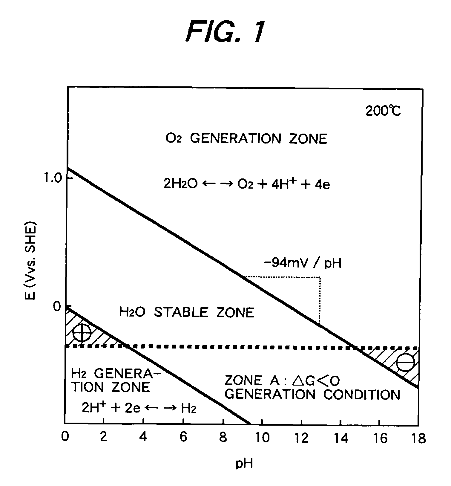
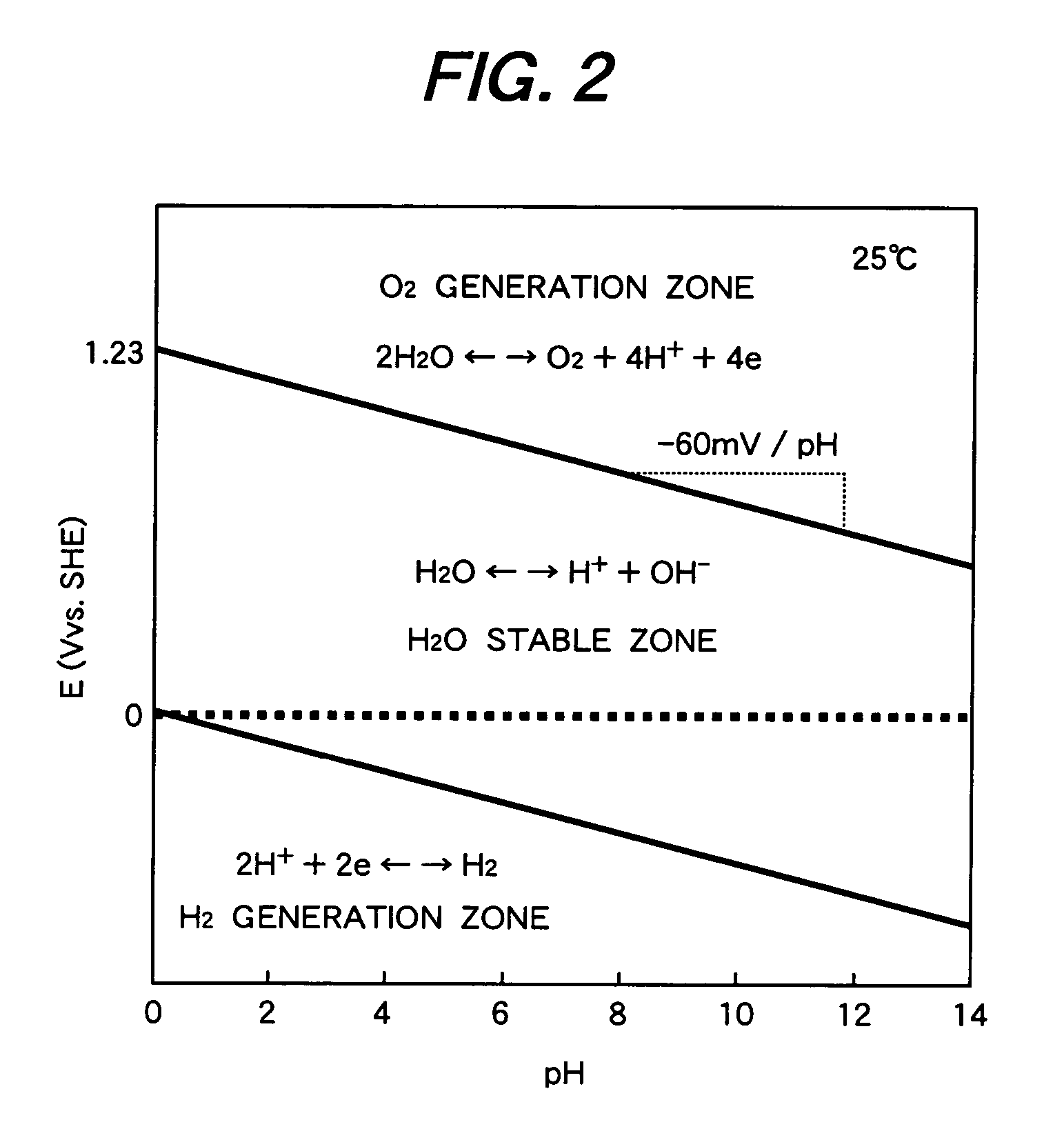
[0039]FIG. 1 is so-called the Pourbaix diagram showing a potential—pH diagram of water at 200° C. FIG. 2 is a potential—pH diagram of water at 25° C. The abscissas in FIGS. 1 and 2 show pH values and ordinate shows standard hydrogen potential.

[0040]In the potential—pH diagrams, the zone between the oxygen generation zone and the hydrogen generation zone shows an area where water exists stably. ΔE is obtained by subtracting the single electrode potential of the equation (4) from the single electrode potential of the equation (3).

[0041]In the diagrams, the cathode reaction is hydrogen generation reaction of (3) and the anode reaction is oxygen generation reaction of (4). The hydrogen generation reaction and the oxygen generation reaction accompany the water dissociation reaction of water shown by the equation (2), where protons accept electrons to form hydrogen and hydroxyl ions release electrons and protons to form oxygen. The overall reaction is expressed by the equation (1).

[0042]I...

embodiment 2

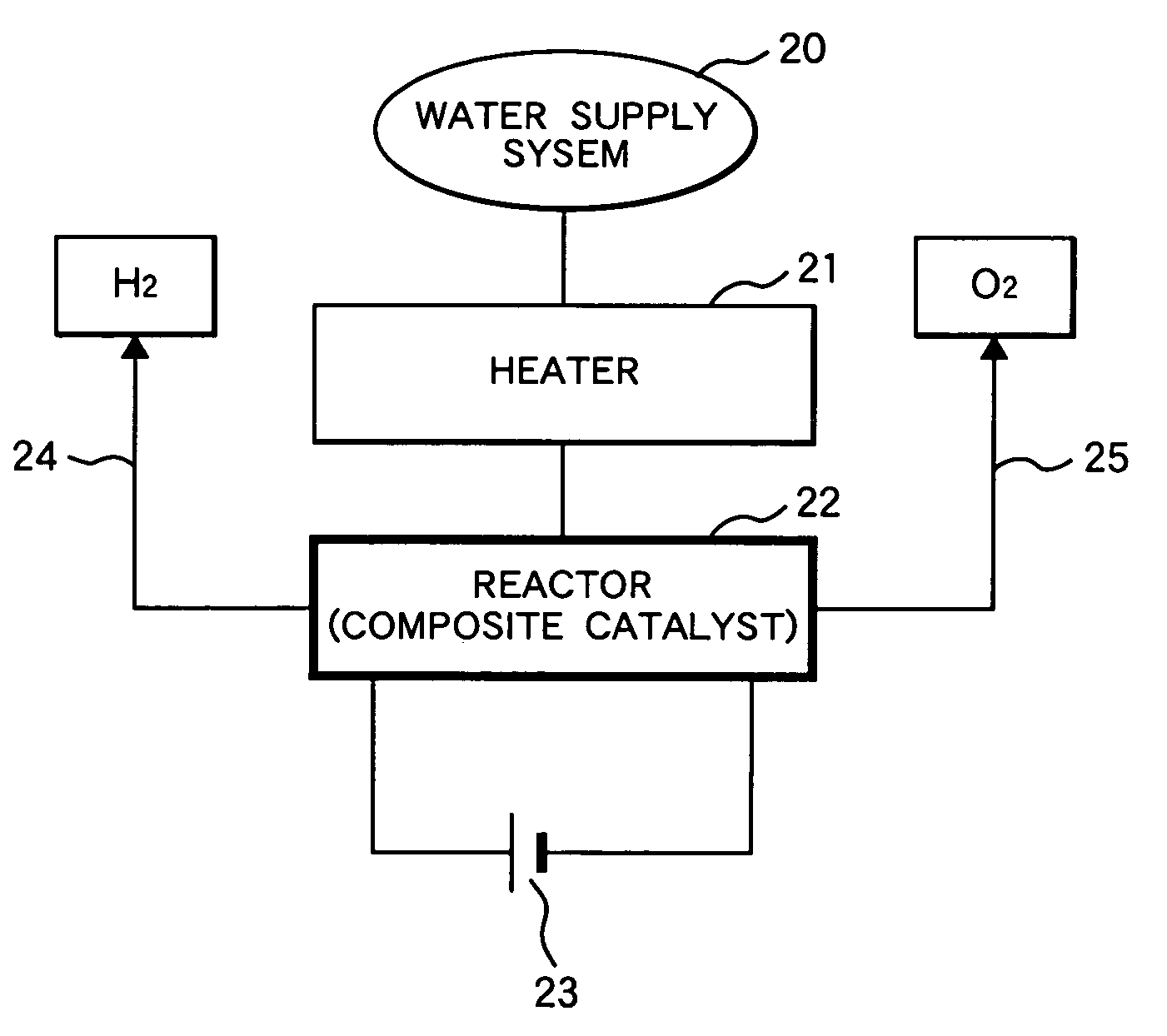
[0062]FIG. 6 is a diagram of a hydrogen production system comprising a catalytic decomposition reactor and a control systems. A mixture of steam and argon gas is supplied to the bottom of the reactor 1 from the water supply source 3. The carrier gas (Ar) is supplied to the steam from the carrier gas supply source 4.

[0063]The reactor is equipped with a heater connected to the electric heater power source 5. The reactor has a pressure vessel to withstand a high pressure. The adsorbed water in the catalysts is maintained in such a state that hydrogen is effectively produced by the micro-cells. The reactor is equipped with a pair of electrode for polarizing the micro-cells in the catalysts. As a result, the micro-cells decompose water to produce hydrogen and oxygen separately. The power source applies a potential between the electrodes of a voltage such as 1.0 volt, which is sufficient to polarize the micro-cells. Produced hydrogen and oxygen are discharged from the upper part of the re...


PUM

PropertyMeasurementUnit
temperatureaaaaaaaaaa
sizeaaaaaaaaaa
temperatureaaaaaaaaaa

Abstract

A method of catalytically decomposing water, which comprises contacting water with a composite catalyst comprising a solid acid catalyst and a solid base catalyst at an elevated temperature, wherein the composite catalyst contains the solid acid catalyst in an amount of 36 to 65% by weight and the balance being the solid base catalyst, and wherein the temperature is higher than a temperature at which pH values of the (H2O / O2 redox) potential and (H2O / H2 redox) potential are equal to each other, the redox potentials being given by a water potential—pH value diagram.

Description

CLAIM OF PRIORITY[0001]This application claims priority from Japanese application serial No. 2004-343249, filed on Nov. 29, 2004, the content of which is hereby incorporated by reference into this application.FIELD OF THE INVENTION[0002]The present invention relates to a method, an apparatus and a catalyst for catalytically decomposing water at low temperatures to produce hydrogen and oxygen.RELATED ART[0003]Nowadays a development of clean energy is urged from the view points of exhaustion of fossil fuels and preservation of the global environment. Utilization of hydrogen energy is one of typical examples of clean energy among the resources; however, hydrogen hardly exists by itself on the earth. Accordingly, a technology for supply hydrogen is the key for development of hydrogen energy. At present, many investigations of hydrogen production have been made; among them, a technology for producing hydrogen from water that is almost unexhaustible on the earth is particularly important....

Claims


Application Information

Patent Timeline
Patent Type & Authority Patents(United States)
IPC IPC(8): C01B3/04B01J21/06
CPCB01J21/12B01J23/02C25B1/04C25B9/00B01J35/0006Y02E60/364Y02E60/366Y02E60/36
Inventor SAKAI, MASANORIFUJII, KAZUMIARAKI, KENJI
Owner HITACHI LTD
Why Eureka
Try Eureka