Method for weighing items moving over a weighing plate in succession

a weighing plate and item technology, applied in the direction of weighing apparatus, ticket-issuer apparatus, instruments, etc., to achieve the effect of increasing the throughput of mail items through the processing system

Inactive Publication Date: 2008-04-15
FRANCOTYP POSTALIA
View PDF16 Cites 7 Cited by
  • Summary
  • Abstract
  • Description
  • Claims
  • Application Information

AI Technical Summary

Benefits of technology

[0014]An object of the invention is to better utilize existing capabilities of mail processing components to increase the throughput of mail items through a processing system.
[0015]More specifically, an object of the invention is to achieve smaller intervals between the mail pieces without increasing the transport speed in the scale region relative to the transport speed in a subsequent (downstream) device.
[0017]In accordance with the invention, the subsequent (next) mail piece is already conducted to the weighing plate after a stable measurement result exists for the last-weighted (i.e. the immediately preceeding) mail piece. The weight of the subsequent mail piece is determined by calculation addition (mail piece in addition to the weighing plate) or by subtraction (a mail piece leaves the weighing plate). If the mail pieces are letters, under the assumptions of the smallest possible separations between the letters and the shortest-allowed and light letters (synonymous with the shortest measurement time) multiple letters can be simultaneously on the weighing plate. Generally, two letters can be simultaneously on the weighing plate. This corresponds to an increase of the throughput by at least double relative to the conventional prior art. The smallest-possible interval between two letters is between 20 to 50% of the shortest letter length and is established by the conditions in the sorting. The increase of the throughput in turn enlarges the tolerance for adaptation to the processing speed of the upstream and downstream components of the mail processing system.

Problems solved by technology

This means that the minimum separation between two successive mail pieces amounts to more than one weighing plate length; that is particularly disadvantageous in the case of short, light letters.

Method used


Image

  • Method for weighing items moving over a weighing plate in succession
  • Method for weighing items moving over a weighing plate in succession
  • Method for weighing items moving over a weighing plate in succession

Examples


Embodiment Construction

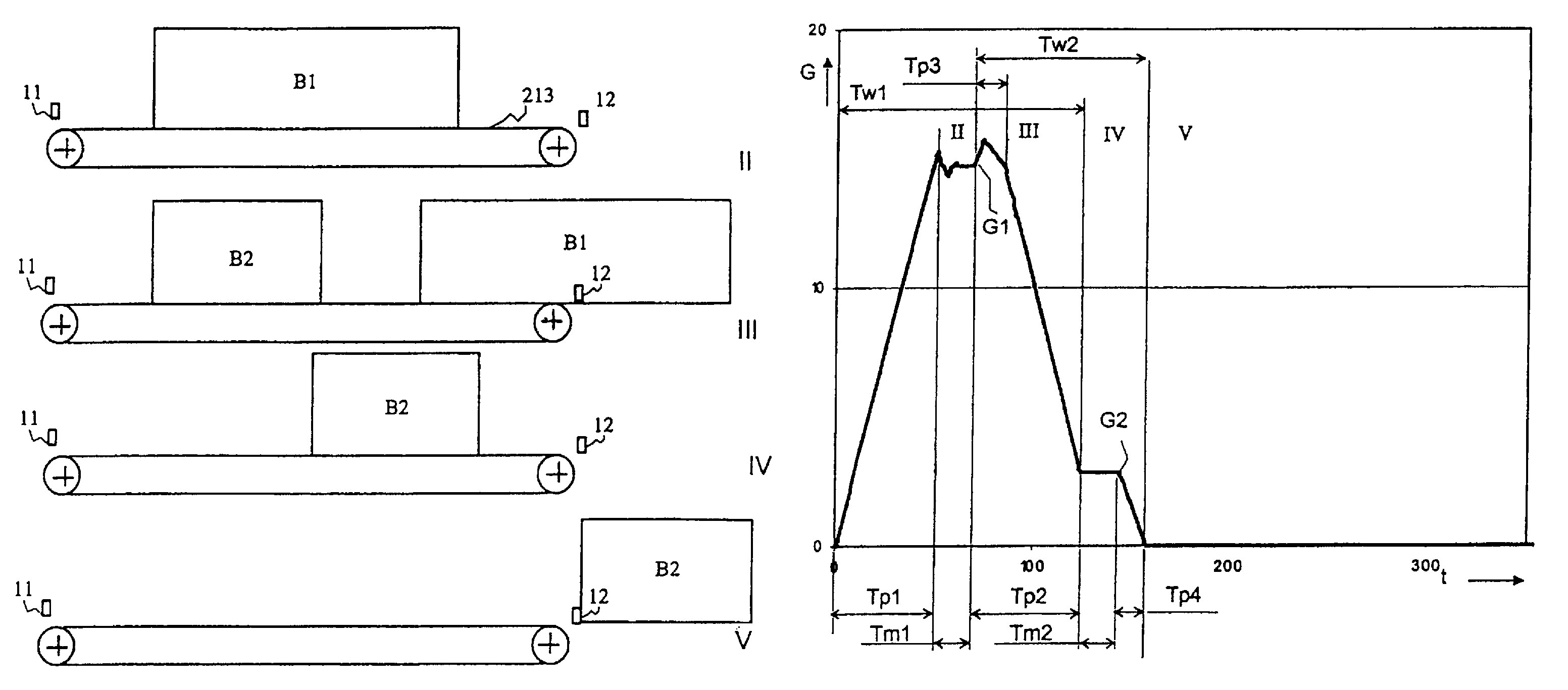
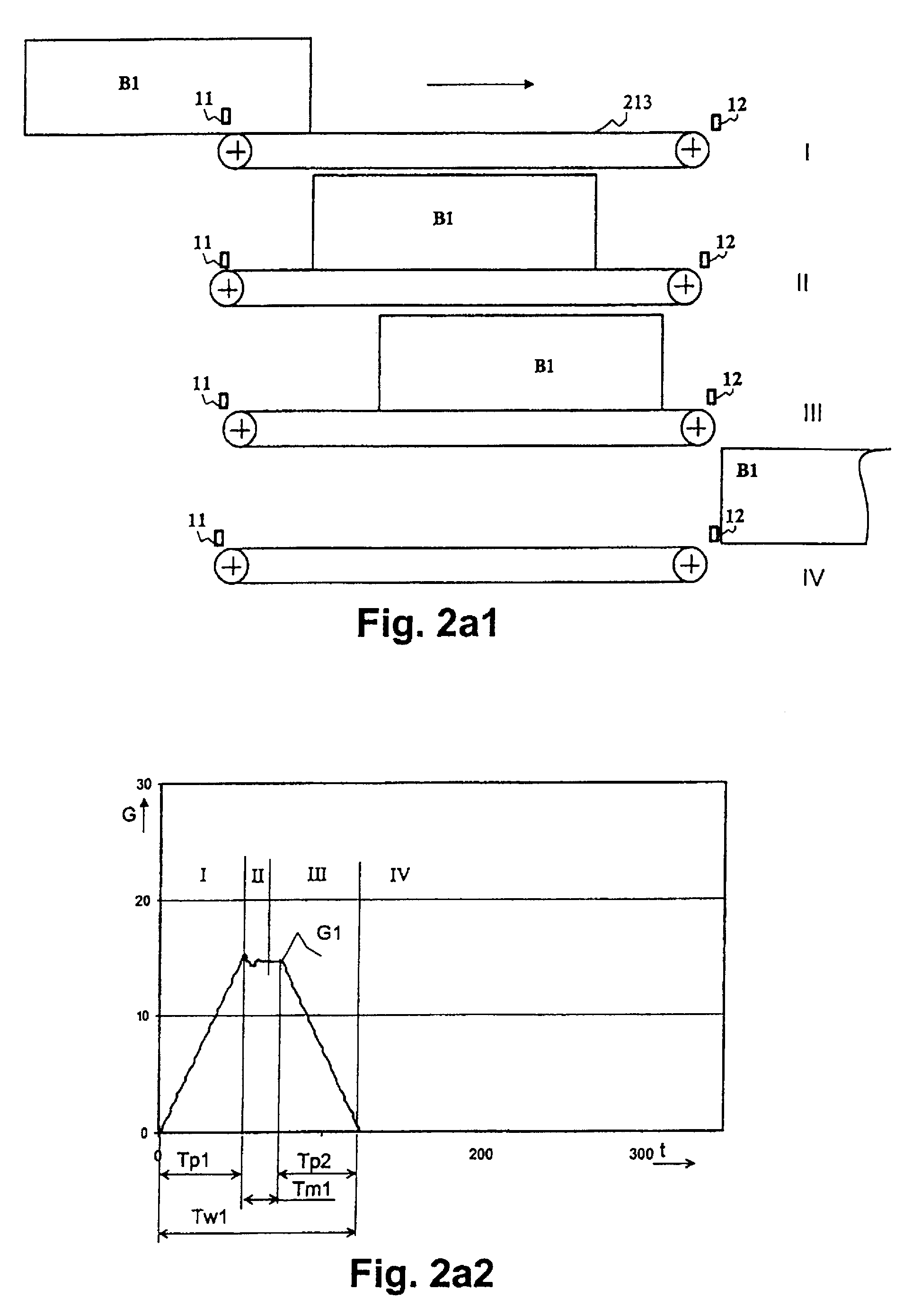
[0027]The representation below is partially schematized for simplification and for easier understanding. For brevity, in the following the term “letter” is used to represent all types of mail goods or mail items capable of being weighed in the manner described below.

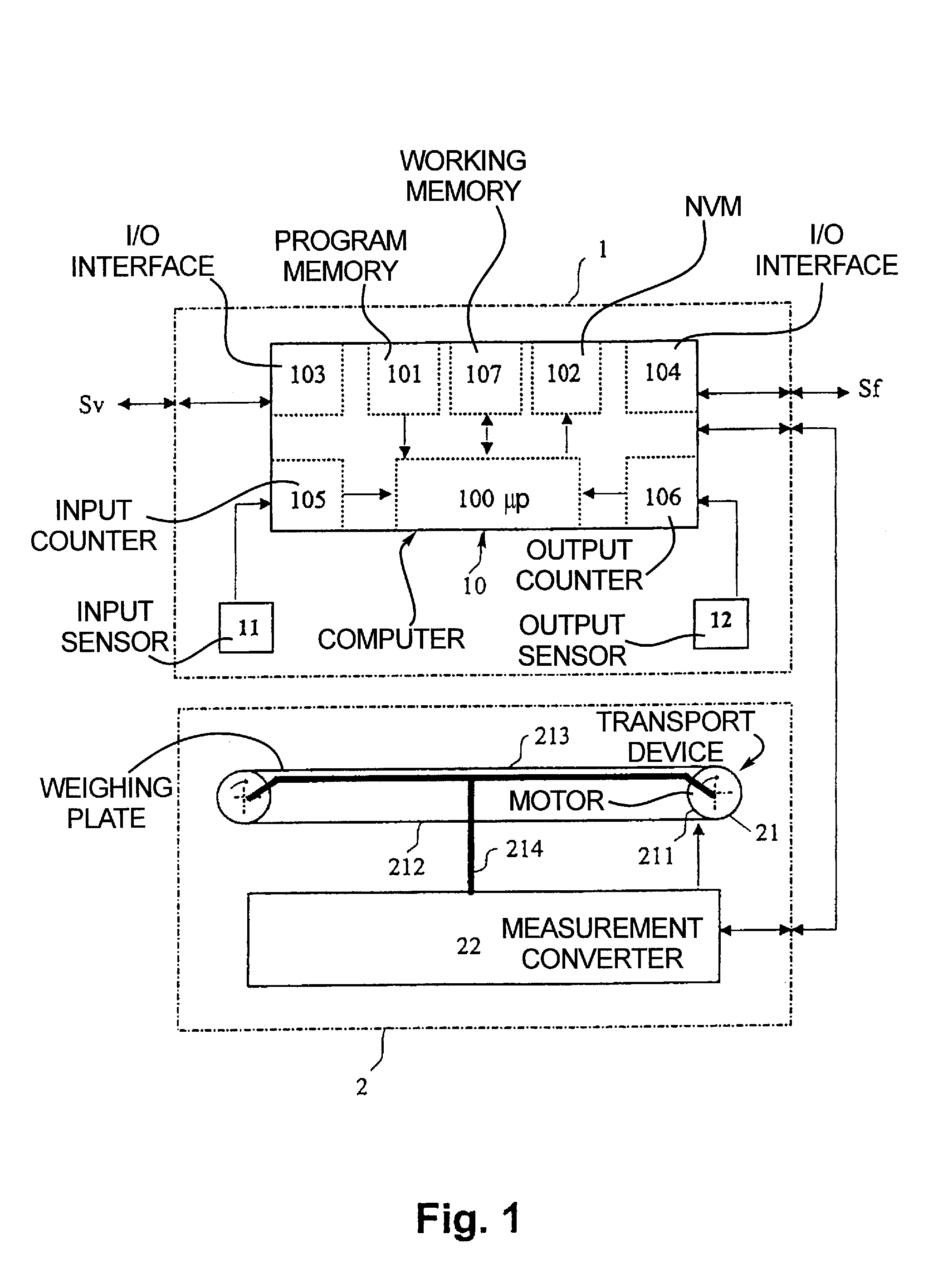
[0028]As shown in FIG. 1, a dynamic scale for implementation of the inventive method is basically composed of a control part 1 and a transport and weighing part 2.

[0029]The control part 1 includes a computer 10 with a microprocessor (μp) 100, a program memory 101 for the operating software, a non-volatile memory (NVM) 102 for operating data such as transport speed or measurement precision, a working memory 107 executed as a RAM, an input / output interface 103 on the input side, an input / output interface 104 on the output side, an input counter 105 for incoming letters B, an output counter 106 for outgoing letters B, an input sensor 11 and an output sensor 12.

[0030]The input / output interface 103 on the input side is connec...


PUM


Abstract

In a method for weighing a number of items, such as letters to be franked, on a transport belt that moves over a weighing plate, the base of which is formed by the transport belt, the transport speed of the belt is slowed within a measurement time range, that starts from the beginning of a weighing event on the weighing plate until a stable weight measurement occurs, and is accelerated outside of this measurement time range, after the occurrence of a stable weight value for a current item on the weighing plate, the next-following item is transported onto the weighing plate by the belt, and the weight of the next-following item is determined by the weight increase due to inflow of the next-following item and the weight decrease due to outflow of the current item.

Description

BACKGROUND OF THE INVENTION[0001]1. Field of the Invention[0002]The invention concerns a method for weighing items moving over a weighing plate in succession, particularly letters standing on edge. The method is suitable for users of mail processing systems with a dynamic scale and a postage-calculating franking machine, or with a dynamic postage calculation scale and a franking machines.[0003]2. Description of the Prior Art[0004]Mail processing systems typically include a mail item sorting (separating) device (see DE 27 17 721 A1 and DE 37 31 525 C2).[0005]Such mail processing systems normally are described for mixed mail. This means a load range of 3 to 1000 grams, a load thickness between 0.5 and 20 millimeters and load lengths between 100 and 353 millimeters.[0006]A letter sorting device is known (see DE 199 12 807 A1) that is equipped with means for determination of the letter dimensions. The data so determined are conducted to a following device such as a scale and / or franking...

Claims


Application Information

Patent Timeline
Patent Type & Authority Patents(United States)
IPC IPC(8): G01G19/414
CPCG01G19/005G01G19/03G01G19/4148
Inventor HUBLER, UWEKUNDE, CHRISTOPHSCHMIDT-KRETSCHMER, MICHAEL
Owner FRANCOTYP POSTALIA
Why Eureka
Try Eureka