[0053]It will be appreciated that the network of FIG. 4 is a significantly simplified relative to large and complex interconnect networks of some actual
integrated circuit designs. A given victim net may have multiple first order aggressors. A given first order aggressor net may have multiple second order aggressor nets. It will be further understood that
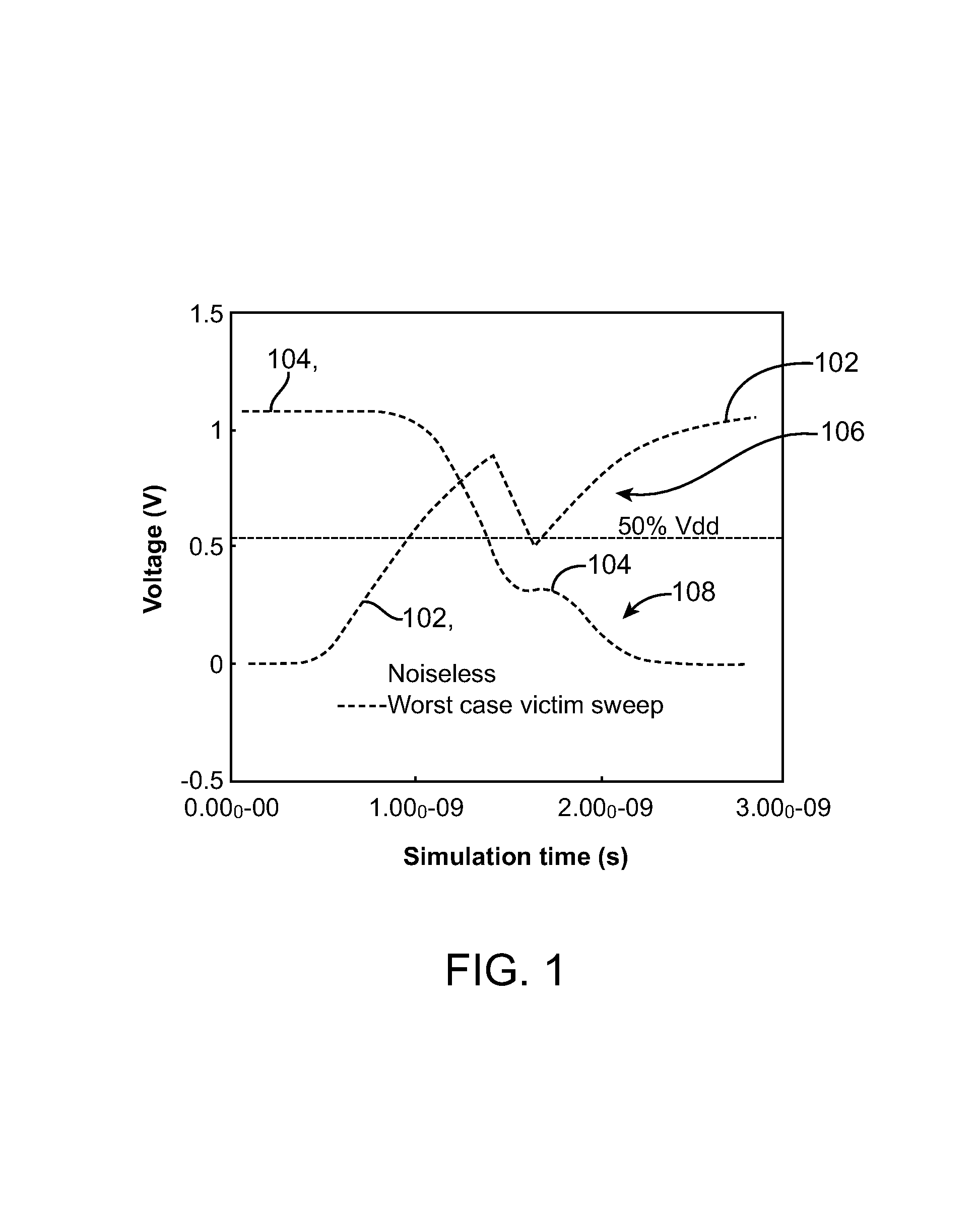
crosstalk delay
change analysis through
simulation of a large and complex interconnect network, especially one with nonlinear (models of) aggressor drivers, could be prohibitively expensive. One
advantage of the present invention is that it can provide accurate
crosstalk delay
change analysis without the need for such
simulation.
[0054]More particularly, in accordance with one novel aspect of an embodiment of the present invention, aggressor waveforms for fast transitions of aggressors are pre-computed on aggressor nets using only prescribed closest neighbors, victim and second order aggressors. The computation is performed using a (nonlinear) ViVo current model (CM) and II-model of the load, which is computed for the network including aggressor nets and its neighbor nets. The CM and
load model used in a present embodiment are described below with reference to FIGS. 6A-6B. As used herein, a fast transition of an aggressor is a rising or falling waveform of
voltage transition on the output of an aggressor's driver or aggressor net, which is the fastest among possible sensitizations and drivers. Thus, if an aggressor net has multiple drivers with multiple sensitizations, the fast transition is computed using the combination of driver and
sensitization that gives the fastest aggressor transition. The fastest aggressor transition is pre-computed because it is likely to be an aggressor to several victim nets, and calculating in advance gives significant run time improvement. In addition, during the computation of fast transition on aggressor nets the effects of neighbors nets are also accounted for, which effectively means that during a subsequent delay change calculation on a victim net, second order aggressors are also accounted for. In a present implementation, a piece-wise linear (PWL) aggressor waveform is used. The prescribed neighbors are nets having
coupling capacitance to the aggressor net in which the fast transition is calculated.
[0055]During
crosstalk delay change determinations in accordance with one embodiment of the invention, only first order aggressors of a victim net are considered. These aggressors' nonlinear drivers are replaced with pre-computed
voltage sources (i.e., the pre-computed aggressor waveforms) determined during the fast transition analysis. The aggressor waveforms, however, are computed using (a model of) nonlinear driver of the aggressor net and accounting for the
impact upon the aggressor from other nets closest to the aggressor net (that is, second-order aggressors of the victim under scrutiny).
[0056]Conversely, in the case of crosstalk delay
change analysis, a transition on the victim net can
impact transitions on aggressor nets. Just replacing the aggressor's driver with a
voltage source would assume an infinite
admittance of the switching aggressor driver and would
neglect transition on the victim net
impact upon aggressors. A Thevenin
equivalent circuit is substituted for an aggressor driver in order to account for the finite
admittance of the switching aggressor drivers.
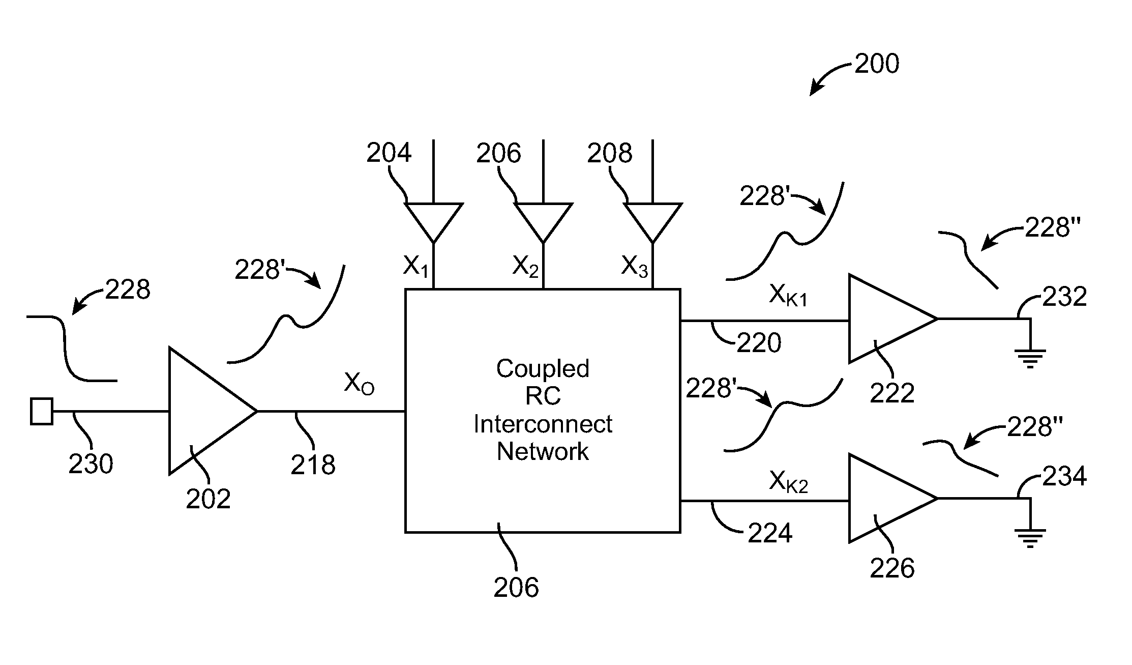
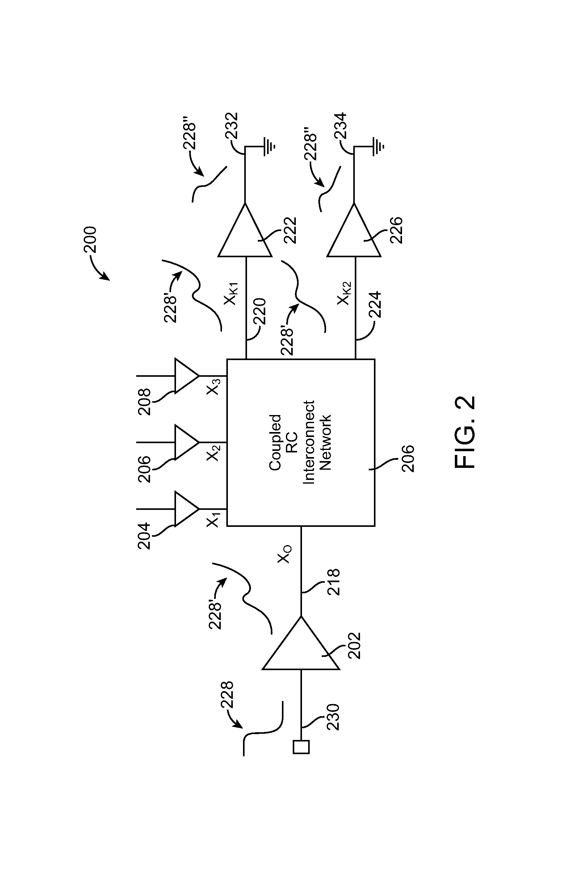
[0057]FIG. 5 is an illustrative drawing of one example circuit 500 that can be used to pre-compute fast transitions on aggressor nets. Parasitic resistors are omitted from the figure for the sake of
clarity. It will be appreciated that at some point in the course of performing timing
delay analysis of an
integrated circuit design, a given net may be a victim net and at other points it may be an aggressor net. Likewise, at some point in an overall delay change analysis process, a given net may be a first order aggressor and at another point it may be a second order aggressor net.
[0058]Accordingly, computation of fast transitions (rising and falling) on output pins of gates is done in a Breadth-First Search (BFS)
traverse of the whole circuit. Through this traversal, it is ensured that the worst-case (WC) fast transition is pre-computed on all nets. The pre-computed fast transitions are used as a
voltage source (waveform) replacing aggressor drivers during the crosstalk delay change analyses.

