
Digital routing switch matrix for digitized radio-frequency signals

a radio frequency signal and switch matrix technology, applied in the field of switching circuits, can solve the problems of severe losses, high cost of prior art switches, limited flexibility and reconfigurability,

Inactive Publication Date: 2008-04-22
HYPRES
View PDF6 Cites 48 Cited by
  • Summary
  • Abstract
  • Description
  • Claims
  • Application Information

AI Technical Summary

Benefits of technology

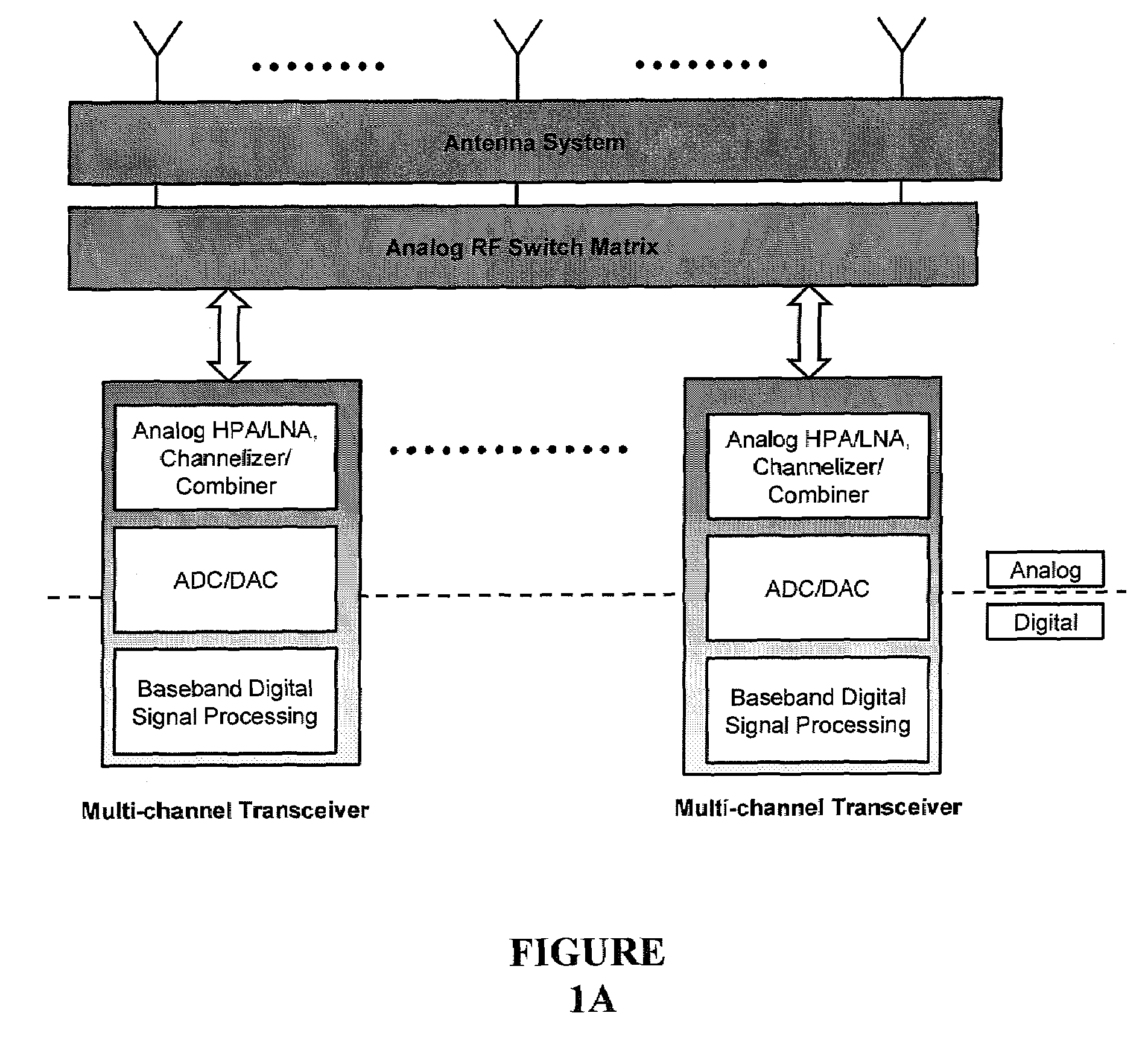
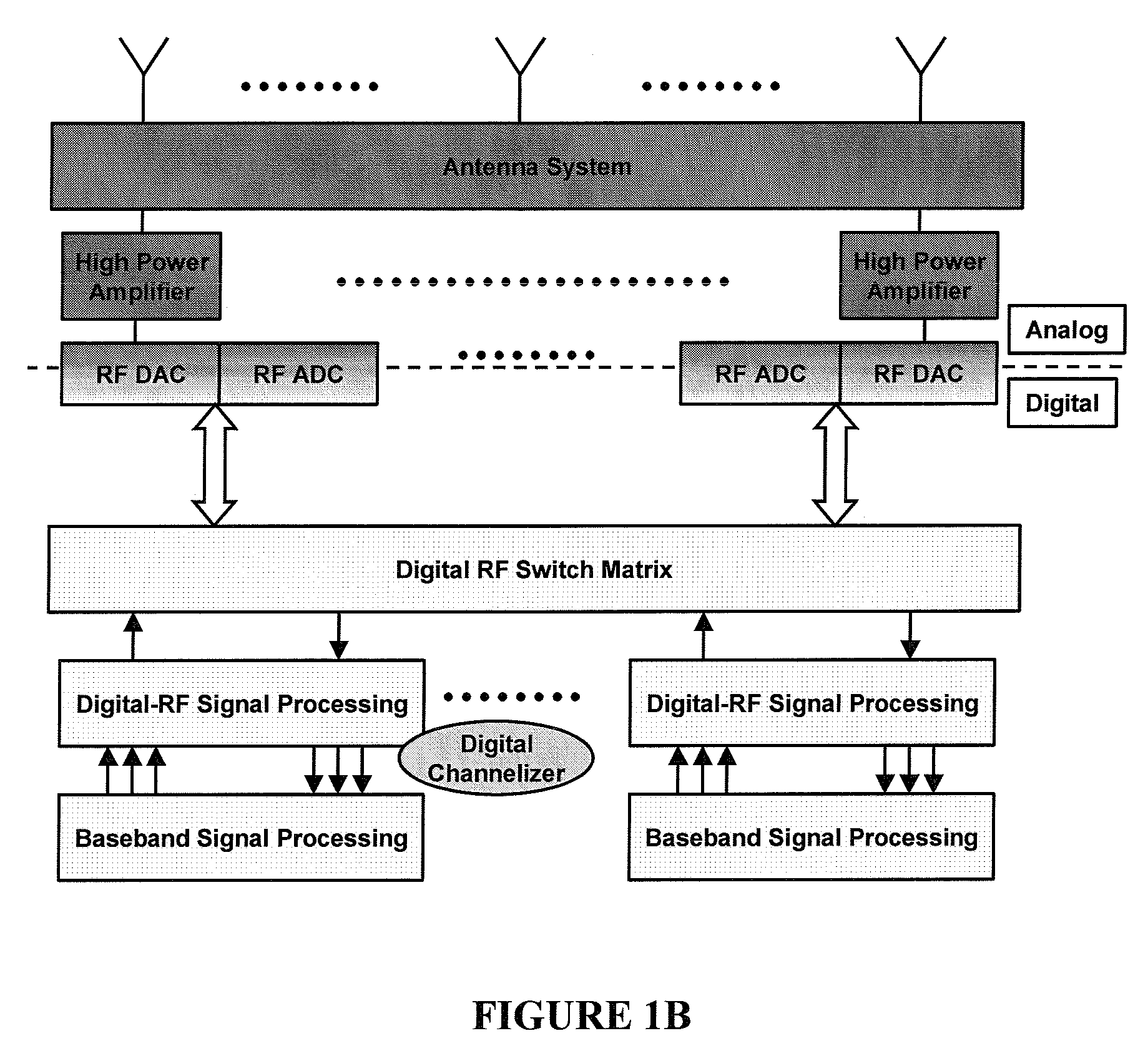
[0014]A multi-carrier, multi-channel RF communication system requires a switch matrix to route various signals between a set of antennas and a set of radio transceivers. This can be carried out most efficiently in the digital domain, but requires the use of ultrafast circuits that can accurately process multi-GHz RF signals.

Problems solved by technology

The prior art switches have been expensive and limited in their flexibility and ability to reconfigure.
In addition, they have severe deficiencies in terms of losses, isolation, cross talk and ability to multicast.

Method used


Image

  • Digital routing switch matrix for digitized radio-frequency signals
  • Digital routing switch matrix for digitized radio-frequency signals
  • Digital routing switch matrix for digitized radio-frequency signals

Examples


Embodiment Construction

I. Basic Switching Cells

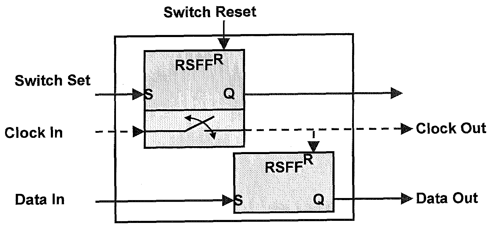
[0030]RSFQ logic, first developed by Likharev, Semenov, and Mukhanov, is built around Josephson junctions (JJs), with lossless propagation of single-flux-quantum (SFQ) voltage pulses, each corresponding to an integrated pulse of 2 mV-ps. Two different types of RSFQ switch cells are described, both of which are well known in the literature: the DC switch and the NDRO switch. In either case, the general principle of operation is the same. A JJ is biased such that an SFQ pulse will cause it to temporarily exceed its critical current and then return to its previous state, thus emitting another SFQ pulse. The switching time, which depends on the critical current density (Jc) of the JJ, is about 2 ps for the Jc=4.5 kA / cm2. This ultrafast switching allows a very high rate (40 Gbps and higher) of SFQ digital signals. Whether or not a switch responds to an input SFQ pulse depends on its designed control conditions (DC bias, control current, or other concurrent digital...


PUM


Abstract

Routing and distribution of radio-frequency (RF) signals is commonly achieved in the analog domain. However, improved performance and simplified circuit architectures may be obtained by first digitizing the RF signal, and then carrying out all routing in the digital domain. A new generation of scalable digital switches has been developed, which routes both the data and clock signals together, this being necessary to maintain the integrity of the digitized RF signal. Given the extremely high switching speeds necessary for these applications (tens of GHz), this is implemented using Rapid-Single-Flux-Quantum (RSFQ) logic with superconducting integrated circuits. Such a digital switch matrix may be applied to either the receiver or transmitter components of an advanced multi-band, multi-channel digital transceiver system, and is compatible with routing of signals with different clock frequencies simultaneously within the same switch matrix.

Description

CROSS REFERENCE TO RELATED APPLICATIONS [0001]This application is related to and claims priority to the following applications: (1) U.S. application Ser. No. 11 / 243,019, filed Oct. 5, 2005, by inventors Alexander Kirichenko, Deepnarayan Gupta, and Saad Sarwana entitled Superconducting Digital Mixer; (2) U.S. application Ser. No. 11 / 243,022, filed Oct. 5, 2005, by inventor Alexander Kirichenko entitled A Digital Programmable Frequency Divider; (3) U.S. application Ser. No. 11 / 243,020, filed Oct. 5, 2005, by inventor Alexander Kirichenko entitled A Digital Programmable Phase Generator; and (4) U.S. application Ser. No. 11 / 360,749, filed Feb. 23, 2006, by inventors Alexander Kirichenko, Timur Filippov, and Deepnarayan Gupta entitled Superconducting Circuit for High-Speed Lookup Table. Each of these applications is hereby incorporated by reference in its entirety.BACKGROUND OF THE INVENTION [0002]1. Field of the Invention[0003]This invention relates to the field of switching circuits an...

Claims


Application Information

Patent Timeline
Patent Type & Authority Patents(United States)
IPC IPC(8): H03K19/195
CPCH03K17/92H04B1/005H04B1/0483H04B1/40H04B1/44
Inventor GUPTA, DEEPNARAYANKIRICHENKO, ALEXANDER F.
Owner HYPRES
Learn More