
Amplitude and phase comparator for microwave power amplifier

a technology of amplitude and phase, which is applied in the field of power amplifiers, can solve the problems of distorted signal output, spurious emission in adjacent and nearby frequency channels, and amplifiers are especially prone to these factors, so as to improve the gain and/or phase error detection system

Inactive Publication Date: 2008-04-22
APPLE INC
View PDF29 Cites 45 Cited by
  • Summary
  • Abstract
  • Description
  • Claims
  • Application Information

AI Technical Summary

Benefits of technology

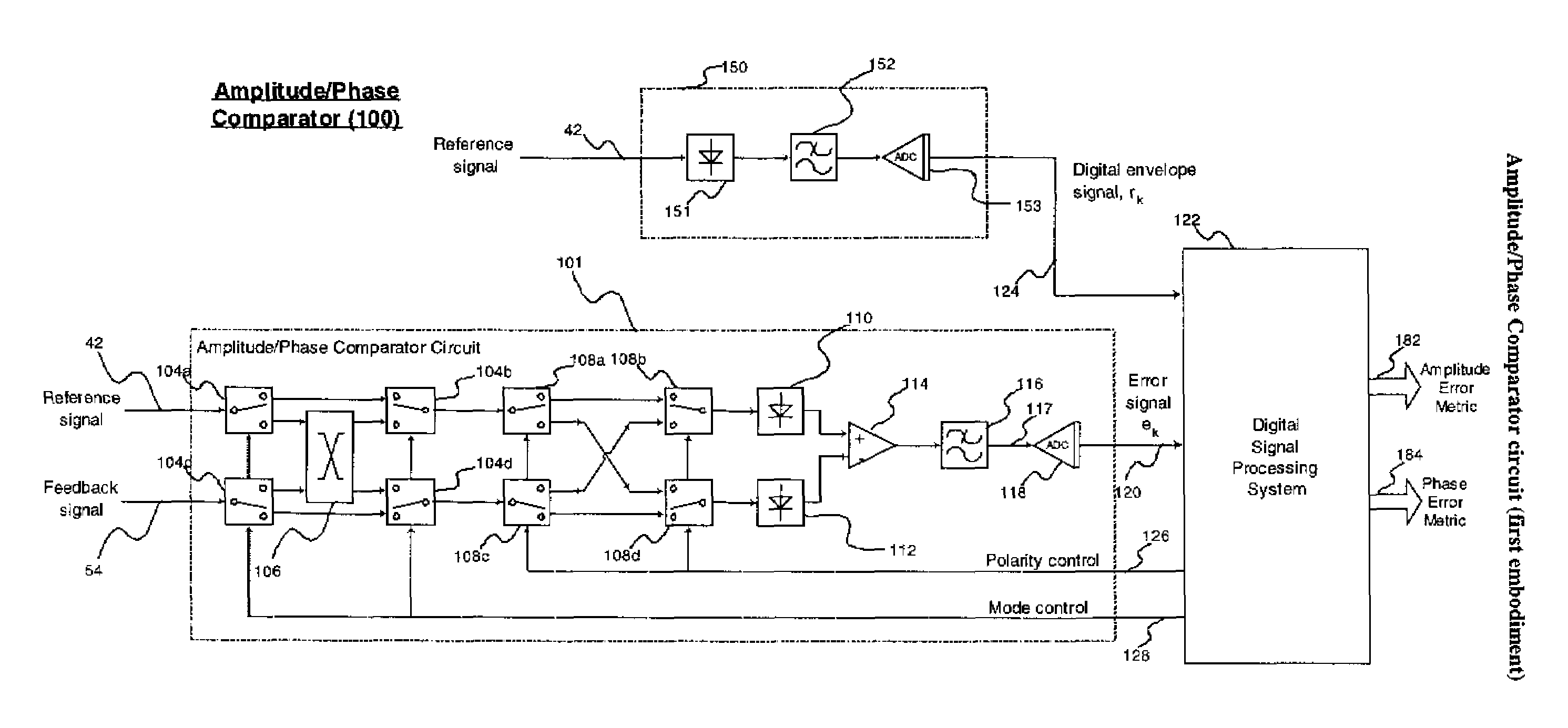
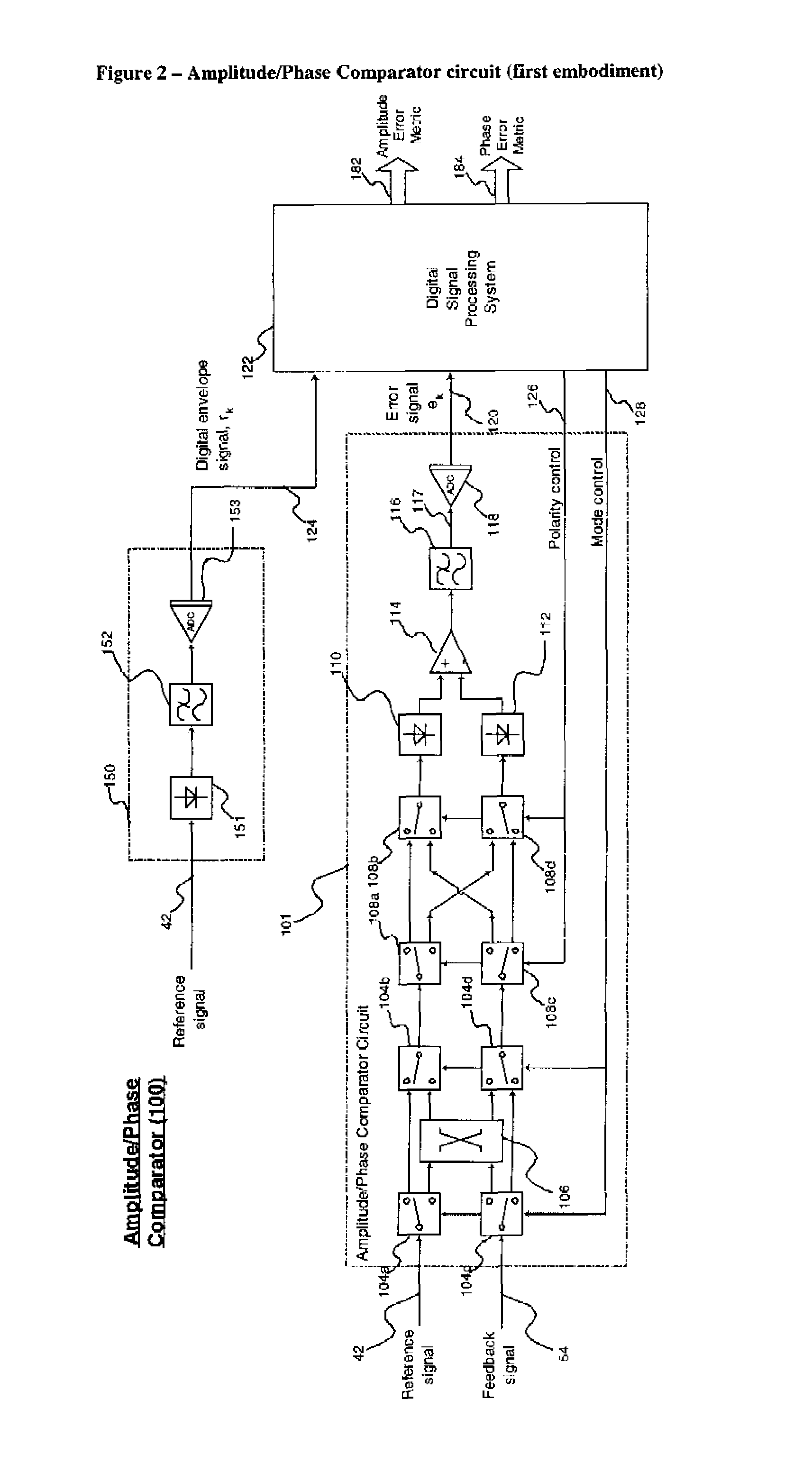
[0014]Capturing two sets of error signals by alternating between two different circuit component sets, and averaging to minimise the distortion introduced by the non-ideal nature of these components provides a more accurate gain / phase error comparator compared with prior art arrangements for predistortion power amplifier stages. The detector has wide signal bandwidth capability and high accuracy, even with a high dynamic range signal, such as those experienced in CDMA-based wireless communication systems. The invention also provides adjustment free operation and immunity to temperature and aging.
[0017]Implementing the difference function in the analogue domain is cheaper than doing this in the digital domain, and has been found in practice to provide more accurate results.
[0021]The DC offset is an important practical improvement which allows the difference or error signal / value to be centred on the middle of the dynamic range of the digitising function by a DC offset control loop.
[0023]Averaging the error values over a predetermined period provides an improved error metric at the output of the comparator, for use by the pre-distorter. This improves the regrowth improvement achievable by the pre-distorter. It also rejects any DC offset applied by the original system.

Problems solved by technology

These applications therefore mean that the amplifiers are especially prone to some of these factors.
This results in a distorted signal output giving rise to the generation of spurious emissions in the adjacent and nearby frequency channels.
Regrowth sidebands are a system problem since they can potentially interfere with neighbouring communication channels.
Feed forward amplifiers also require a separate error amplifier handling similar power levels to the main amplifier which significantly increases the system cost and power consumption.
Depending on the characteristics of the signal, estimating this error to the required degree of accuracy is extremely difficult.
The performance of the error detector system can in fact be limiting on the level of regrowth suppression achievable.
It may also require factory adjustment to optimize spurious performance.

Method used


Image

  • Amplitude and phase comparator for microwave power amplifier
  • Amplitude and phase comparator for microwave power amplifier
  • Amplitude and phase comparator for microwave power amplifier

Examples


Embodiment Construction

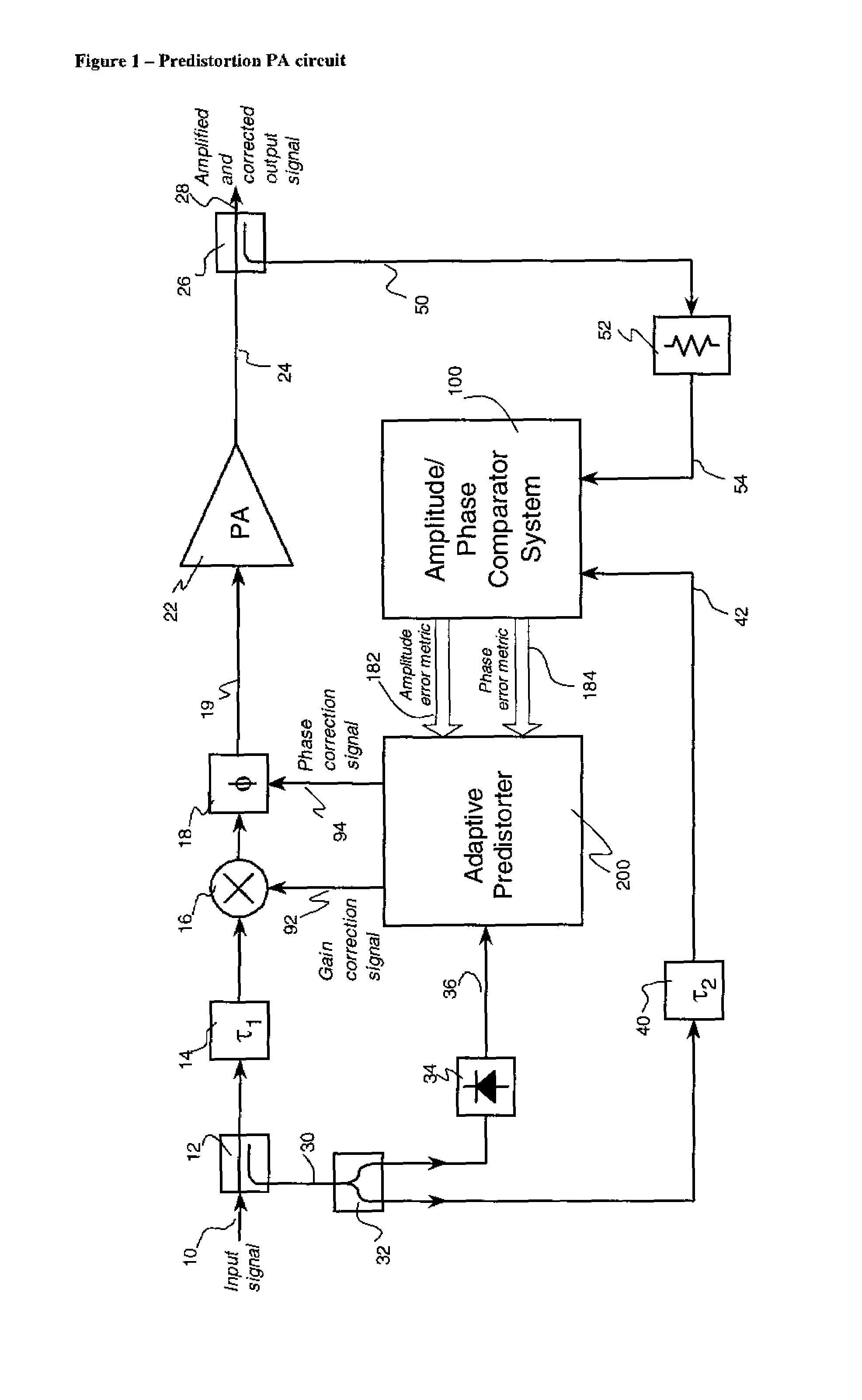
[0052]FIG. 1 shows a predistortion power amplifier circuit architecture incorporating a gain / phase comparator (100) and a predistorter (200) according to the present invention. An RF input signal (10) is applied to an input (19) of a high power amplifier (22) via a directional coupler (12), a first delay line (14), an amplitude modulator (16) and a phase modulator (18). The output (24) of the amplifier (22) provides an amplified output signal (28) which is sampled by a directional coupler (26). The sampled RF output (30) from the directional coupler (12) is applied to a power splitter (32), the outputs of which are connected to an envelope detector (34) and a second delay line (40). The output (36) of the envelope detector is connected to an adaptive pre-distorter subsystem (200). The adaptive pre-distorter subsystem (200) generates two outputs: a gain correction signal (92) which is connected to the control port of amplitude modulator (16); and a phase correction signal (94) which ...


PUM


Abstract

A predistortion power amplifier architecture has a power amplifier which receives an input via an amplitude modulator and a phase modulator. A sample of the output of the amplifier and a sample of the input to the amplifier are applied to an adaptive pre-distorter subsystem. The adaptive pre-distorter generates a gain correction signal which is applied to the amplitude modulator and a phase correction signal which is applied to the phase modulator. This serves to predistort the input signal to the power amplifier to compensate for non-linearities in the power amplifier. A switching arrangement alternately couples a sample of the input and output of the amplifier to a first and a second envelope detector. The outputs of the envelope detectors are applied to a difference amplifier. The switching arrangement has a chopping action on the signals which helps to offset imbalances in the characteristics of the two envelope detectors.

Description

FIELD OF THE INVENTION[0001]The present invention relates to power amplifiers for communications systems and in particular, though not exclusively, to 3G cellular predistortion power amplifiers. The present invention particularly relates to an improved amplitude and phase comparator for such a power amplifier.BACKGROUND OF THE INVENTION[0002]As is well known; microwave power amplifiers are non-linear devices whose amplitude and phase transfer function varies depending on a number of factors including input signal level, frequency, temperature, power supply fluctuations and age. Power amplifiers for wireless communications apparatus typically have to operate throughout a large part of their dynamic range, some of which is highly non-linear. These applications therefore mean that the amplifiers are especially prone to some of these factors. This results in a distorted signal output giving rise to the generation of spurious emissions in the adjacent and nearby frequency channels.[0003]...

Claims


Application Information

Patent Timeline
Patent Type & Authority Patents(United States)
IPC IPC(8): H04L25/49
CPCH03F1/3247H03F1/3282H04L27/368H03F2200/102H03F2200/207H03F2200/321H03F2200/451H03F2200/78H03F2200/99H03F2201/3233
Inventor SMITH, HOWARD JDOLMAN, GRAHAMWIDDOWSON, SCOTT T
Owner APPLE INC
Learn More