Hard coating and its formation method, and hard-coated tool

a technology of hard coating and tool, which is applied in the direction of instruments, elevators, other chemical processes, etc., can solve the problems of insufficient seizure resistance of conventional hard coating tools, and inability to obtain hard coating tools satisfactorily usable under severe cutting conditions. , to achieve the effect of improving oxidation resistance and wear resistance, high hardness and high breakage resistan

Inactive Publication Date: 2008-05-06
HITACHI TOOL ENG LTD
View PDF21 Cites 9 Cited by
  • Summary
  • Abstract
  • Description
  • Claims
  • Application Information

AI Technical Summary

Benefits of technology

[0009]Accordingly, an object of the present invention is to provide a hard coating having excellent oxidation resistance, wear resistance and lubrication, as well as excellent adhesion to a substrate, impact resistance and breakage resistance.
[0011]A further object of the present invention is to provide a hard-coated tool having excellent oxidation resistance, wear resistance, lubrication, impact resistance and breakage resistance, and improved adhesion to the substrate, with the seizure of a work and the diffusion of work elements into the hard coating suppressed in high-temperature cutting, thereby usable for dry cutting, high-speed cutting and high-feed cutting.DISCLOSURE OF THE INVENTION
[0022]When the hard coating of the present invention is applied to wear-resistant members and heat-resistant members required to have high hardness, such as cutting tools, etc., they are provided with extremely improved oxidation resistance and wear resistance, and high breakage resistance because of excellent adhesion to their substrates, and the seizure of works to the tools during dry cutting are suppressed. Accordingly, the hard-coated tool of the present invention can be used at high speed and feed during dry cutting. The high-feed cutting means cutting at feed exceeding 0.3 mm per one edge.

Problems solved by technology

As high-speed metal cutting at a feed per one edge exceeding 0.3 mm becomes prevailing, conventional hard-coated tools have become insufficient in oxidation resistance, wear resistance, peel resistance, seizure resistance, impact resistance, breakage resistance, etc. of hard coatings.
However, because any of the above technologies uses only an arc-discharge ion plating method, edge, they do not necessarily have satisfactory seizure resistance in the cutting of steel, etc., on which seizure tends to occur.
Hard-coated tools satisfactorily usable under severe cutting conditions cannot be obtained without improving the lubrication, impact resistance and breakage resistance of hard coatings with no damage to adhesion to substrates, hardness, oxidation resistance, wear resistance, thermal resistance, etc.
However, these technologies do not provide hard coatings with sufficient adhesion and hardness, failing to sufficiently improve the wear resistance of cutting tools.
However, any of the hard coatings described in the above references fails to meet the demand of having sufficient lubrication, peel resistance, impact resistance and breakage resistance capable of withstanding dry cutting conditions while maintaining oxidation resistance and wear resistance.

Method used


Image

  • Hard coating and its formation method, and hard-coated tool
  • Hard coating and its formation method, and hard-coated tool
  • Hard coating and its formation method, and hard-coated tool

Examples


examples 1-15

, COMPARATIVE EXAMPLES 1-27, AND CONVENTIONAL Examples 1-4

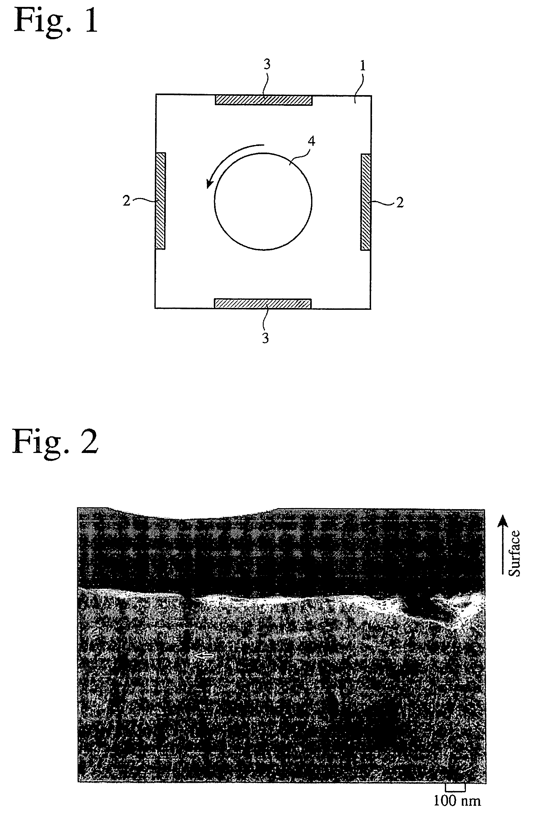
[0075]Using a small vacuum chamber apparatus 1 comprising AIP targets 2 and MS targets 3 as an evaporation source shown in FIG. 1, a hard coating was formed on a substrate of each cemented carbide insert placed on a rotating table 4 in Examples 1-15. The AIP targets 2 were made of alloys having various compositions, and the MS targets 3 were made of metal sulfides. A reaction gas used was an N2 gas, a CH4 gas or an Ar / O2 mixed gas depending on targeted hard coating compositions. To change the distribution of an S content in the hard coating in a lamination direction periodically and smoothly, plasma was generated at a reaction gas pressure of 3.0 Pa, simultaneously by both coating methods of AIP and MS. A substrate temperature was 400° C., and bias voltage was −40 V to −150 V. In Comparative Examples 1-27 and Conventional Examples 1-4, on the other hand, a hard coating was formed on each insert under the same conditions as in...

examples 16-29

, COMPARATIVE EXAMPLES 28-41, AND CONVENTIONAL EXAMPLES 5-11

[0098]Using a small vacuum chamber apparatus 1 shown in FIG. 1 comprising AIP targets 2 and MS targets 3 as evaporation sources, a hard coating was formed on each insert substrate of cemented carbide placed on a rotating table 4. The AIP targets 2 were made of alloys of various compositions, and the MS targets 3 were made of metal sulfides. A reaction gas was an N2 gas, a CH4 gas or an Ar / O2 mixed gas depending on targeted hard coating compositions. To change an S content distribution in the hard coating periodically and smoothly in a lamination direction, the pressure of the reaction gas was set at 3.0 Pa to generate plasma for both film-forming methods of AIP and MS. The substrate temperature was set at 400° C., and bias voltage of −40 V to −150 V was applied.

[0099]The resultant hard-coated inserts were subjected to cutting tests under the following condition 3. Works were made of SKD61 steel (hardness HRC: 45) for die-ca...


PUM

PropertyMeasurementUnit
friction coefficientaaaaaaaaaa
thicknessaaaaaaaaaa
thicknessaaaaaaaaaa

Abstract

A method for forming a multi-layer, hard coating on a substrate, said hard coating comprising at least one metal element selected from the group consisting of transition metal elements of Groups 4a, 5a and 6a in the Periodic Table, Al, Si and B (at least one of said transition metal elements is indispensable), and at least one non-metal element selected from the group consisting of S, O, N and C (S is indispensable), and having a columnar structure comprising columnar crystal grains having pluralities of layers having different S contents, said method comprising placing said substrate in a chamber comprising evaporation sources having different plasma densities and a reaction gas for physical vapor deposition, and alternately bringing said substrate closer to each evaporation source, while keeping said reaction gas in a plasma state and said evaporation sources simultaneously in an active state.

Description

FIELD OF THE INVENTION[0001]The present invention relates to a hard coating having excellent oxidation resistance, wear resistance, peel resistance, seizure resistance, impact resistance, breakage resistance, etc., which covers a substrate of cemented carbide, high-speed steel, die steel, etc., a method for forming such a hard coating, and a tool having such a hard coating.BACKGROUND OF THE INVENTION[0002]As high-speed metal cutting at a feed per one edge exceeding 0.3 mm becomes prevailing, conventional hard-coated tools have become insufficient in oxidation resistance, wear resistance, peel resistance, seizure resistance, impact resistance, breakage resistance, etc. of hard coatings. Accordingly, various technologies have been proposed to improve oxidation resistance, wear resistance, peel resistance, seizure resistance, impact resistance, breakage resistance, etc. of the hard coatings.[0003]JP 2003-225807 A discloses a cutting tool having a hard coating layer exhibiting excellent...

Claims


Application Information

Patent Timeline
Patent Type & Authority Patents(United States)
IPC IPC(8): C23C14/00C23C14/06C23C28/04C23C30/00
CPCB82Y30/00C23C14/06C23C30/005C23C28/044Y10T428/265B66B5/027B66B11/0226
Inventor KUBOTA, KAZUYUKI
Owner HITACHI TOOL ENG LTD
Why Eureka
Try Eureka