Circularly polarized microstrip antenna and radio communication apparatus including the same

a microstrip antenna and radio communication technology, applied in the direction of antennas, antenna details, basic electric elements, etc., can solve the problems of increasing manufacturing costs, difficult to insert the feeding pin b>34, b> into the dielectric substrate, etc., to achieve satisfactory resonance for generating circularly polarized waves, reduce the length of the signal line that overlaps the emitting electrode, and achieve the effect of more reliable resonan

Inactive Publication Date: 2008-05-06
MURATA MFG CO LTD
View PDF23 Cites 5 Cited by
  • Summary
  • Abstract
  • Description
  • Claims
  • Application Information

AI Technical Summary

Benefits of technology

[0018]According to the present invention, the coplanar signal line provided on the back surface of the dielectric substrate extends from an edge of the back surface of the dielectric substrate to an intermediate position between the edge of the back surface of the dielectric substrate and a center position of the emitting electrode on the back surface of the dielectric substrate. In other words, the length of the signal line for feeding the emitting electrode according to the present invention is shorter than the length of a signal line for feeding an emitting electrode that extends from en edge of a back surface of a dielectric substrate to a center position of the emitting electrode on the back surface of the dielectric substrate. Therefore, according to the present invention, a portion of the signal line that overlaps the emitting electrode can be reduced in length or eliminated.
[0024]On the other hand, antennas having a tri-plate structure (i.e., antennas having a three-layer structure including an emitting electrode, a feeding electrode, and a ground electrode disposed with dielectric layers interposed therebetween) are suggested (see, for example, Patent Document 4). In this structure, the emitting electrode, the feeding electrode, and the ground electrode are arranged at different layer positions. Therefore, the manufacturing process is complex and the material cost is increased since the number of dielectric layers is increased. In comparison, according to the present invention, since the signal line for feeding the emitting electrode and the ground electrode are both formed on the back surface of the dielectric substrate, the signal line for feeding the emitting electrode and the ground electrode can be formed simultaneously. Accordingly, the manufacturing process can be simplified. In addition, since the amount of dielectric material used can be reduced, the material cost can be reduced.

Problems solved by technology

However, in mass production, for example, it is extremely difficult to insert the feeding pin 34 into the dielectric substrate 31 as designed in all of the products.
Therefore, there are problems that a cumbersome task of connecting the coaxial cable to the antenna structure 30 is necessary and the manufacturing cost is increased.
Therefore, there is a problem that satisfactory resonance for generating the circularly polarized waves cannot be obtained by the emitting electrode 45 because of the reason described below and it is difficult for the antenna structure 43 to function as a circularly polarized antenna.

Method used


Image

  • Circularly polarized microstrip antenna and radio communication apparatus including the same
  • Circularly polarized microstrip antenna and radio communication apparatus including the same
  • Circularly polarized microstrip antenna and radio communication apparatus including the same

Examples


first embodiment

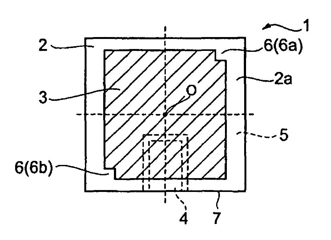
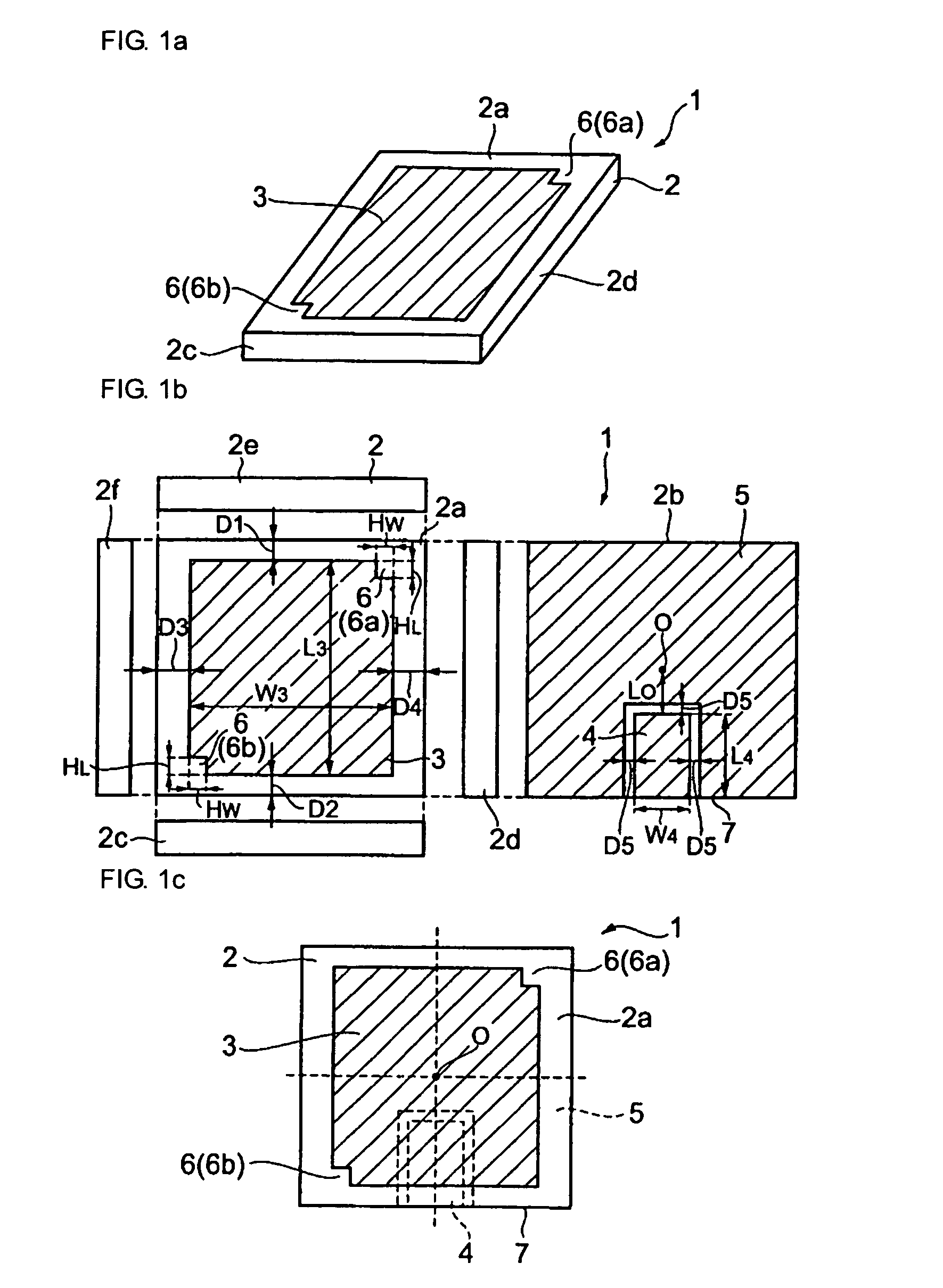
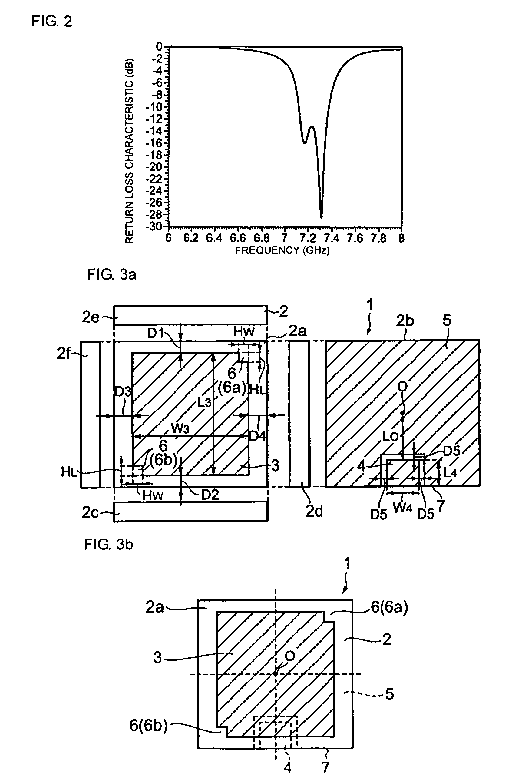
[0051]FIG. 1a is a schematic perspective view of a circularly polarized microstrip antenna according to a FIG. 1b is a schematic development of the circularly polarized microstrip antenna shown in FIG. 1a. FIG. 1c is a schematic top plan view of the circularly polarized microstrip antenna shown in FIG. 1a.

[0052]A circularly polarized microstrip antenna 1 according to the first embodiment includes a dielectric substrate 2. The dielectric substrate 2 has a rectangular plate-like shape. The dielectric substrate 2 is composed of a dielectric material with a dielectric constant of 6 or more. An emitting electrode 3 is formed on a front surface 2a of the dielectric substrate 2. A coplanar signal line 4 for feeding the emitting electrode 3 is formed on a back surface 2b of the dielectric substrate 2. In addition, a ground electrode 5 is formed on the back surface 2b of the dielectric substrate 2 such that the ground electrode 5 covers substantially the entire area excluding the region wh...

second embodiment

[0070]In the second embodiment, the signal line 4 for feeding the emitting electrode 3 does not overlap the emitting electrode 3, and is shaped such that the width at the inner end of the signal line 4 is larger than that at the end on the edge of the bottom surface of the dielectric substrate. However, even when the width of the signal line 4 is constant over the entire length thereof from the end on the edge of the back surface of the dielectric substrate to the inner end, if, for example, the width of the signal line 4 is large and strong electromagnetic coupling can be obtained between the signal line 4 and the emitting electrode 3, the signal line 4 can be structured such that the signal line 4 does not overlap the emitting electrode 3. In addition, even when the width of the signal line 4 at the inner end thereof is larger than that at the end on the edge of the back surface of the dielectric substrate, the signal line 4 may be structured so as to overlap the emitting electrod...


PUM


Abstract

A circularly polarized microstrip antenna includes a dielectric substrate having only an emitting electrode for generating circularly polarized waves on a front surface of the dielectric substrate and a coplanar signal line for feeding the emitting electrode and a ground electrode on a back surface of the dielectric substrate. The ground electrode covers the entire area of the back surface of the dielectric substrate excluding a region in which the signal line is provided. The signal line extends from an edge of the back surface of the dielectric substrate to an intermediate position between the edge of the back surface of the dielectric substrate and a center position O of the emitting electrode on the back surface of the dielectric substrate. Thus, a circularly polarized microstrip antenna whose circular polarization characteristic can be easily improved and whose manufacturing cost and size can be easily reduced is provided.

Description

CROSS REFERENCE TO RELATED APPLICATIONS[0001]The present application is a continuation of International Application No. PCT / JP2005 / 005550, filed Mar. 25, 2005, which claims priority to Japanese Patent Application No. JP2004-157983, filed May 27, 2004, the entire contents of each of these applications being incorporated herein by reference in their entirety.FIELD OF THE INVENTION[0002]The present invention relates to a circularly polarized microstrip antenna for performing radio communication using circularly polarized waves and a radio communication apparatus including the circularly polarized microstrip antenna.BACKGROUND OF THE INVENTION[0003]FIG. 8a illustrates a perspective view of an example of a circularly polarized antenna structure, and FIG. 8b illustrates a schematic sectional view of the circularly polarized antenna structure shown in FIG. 8a (see, for example, Patent Document 1). This circularly polarized antenna structure 30 includes a dielectric substrate 31. An emittin...

Claims


Application Information

Patent Timeline
Patent Type & Authority Patents(United States)
IPC IPC(8): H01Q1/38H01Q9/04H01Q13/08
CPCH01Q9/0428H01Q1/38H01Q9/0457
Inventor KUSHIHI, YUICHI
Owner MURATA MFG CO LTD
Why Eureka
Try Eureka