Autoclavable imager assembly

an imager and autoclavable technology, applied in the field of endoscopy and imaging systems, can solve the problems of loss of transparency, affecting the performance of the inability to directly see the operating field by the person carrying out the operation, so as to improve the image quality and the dynamic response

Active Publication Date: 2008-05-06
MEDIGUS LTD
View PDF22 Cites 59 Cited by
  • Summary
  • Abstract
  • Description
  • Claims
  • Application Information

AI Technical Summary

Benefits of technology

[0042]d) a display system capable of displaying the outputted image in a continuous and non-interlaced mode, wherein the circuitry for extracting each line of th

Problems solved by technology

Minimal access therapy and/or diagnostics are generally carried out within body cavities and, therefore, the operating field cannot be directly viewed by the person carrying out the operation.
However, their performance is affected by the amount of light available in the endoscope, which is dependent upon the size of the illumination means such as the fibers used to transmit the light from a remote source to the operating area, or the Light Emitting Diodes (LEDs) used to illuminate the cavity, e.g., stomach, colon, etc.
This sensitivity results from several causes, one being that the imaging sensor, the objective lens system, and other components of the imager are usually encapsulated utilizing transparent adhesive materials that may lose their transparency as a result of the temperature and pressure involved in the autoclaving process.
The loss of transparency is accompanied by a substantial deterioration of the optical qualities of the imager.
Another cause of the sensitivity is problems caused by leakage resulting from the pressure of the steam involved in autoclaving.
Additionally, signal distortions result, during medical and industrial procedures, when the environment is hot in comparison to the room temperature or due to residual heat after the autoclaving procedure.
However, although this spaced construction resolves the autoclaving drawbacks discussed above, it also substantially enlarges the imager dimensions.
Thus it is not a viable solution when it is necessary to include miniature electrical circuitry in the vicinity of the imaging sensor, as is the case in applications utilizing relatively small imaging sensors.
One of the difficulties that must be solved in designing increasingly smaller camera heads is that the density of photons received by

Method used


Image

  • Autoclavable imager assembly
  • Autoclavable imager assembly
  • Autoclavable imager assembly

Examples


Embodiment Construction

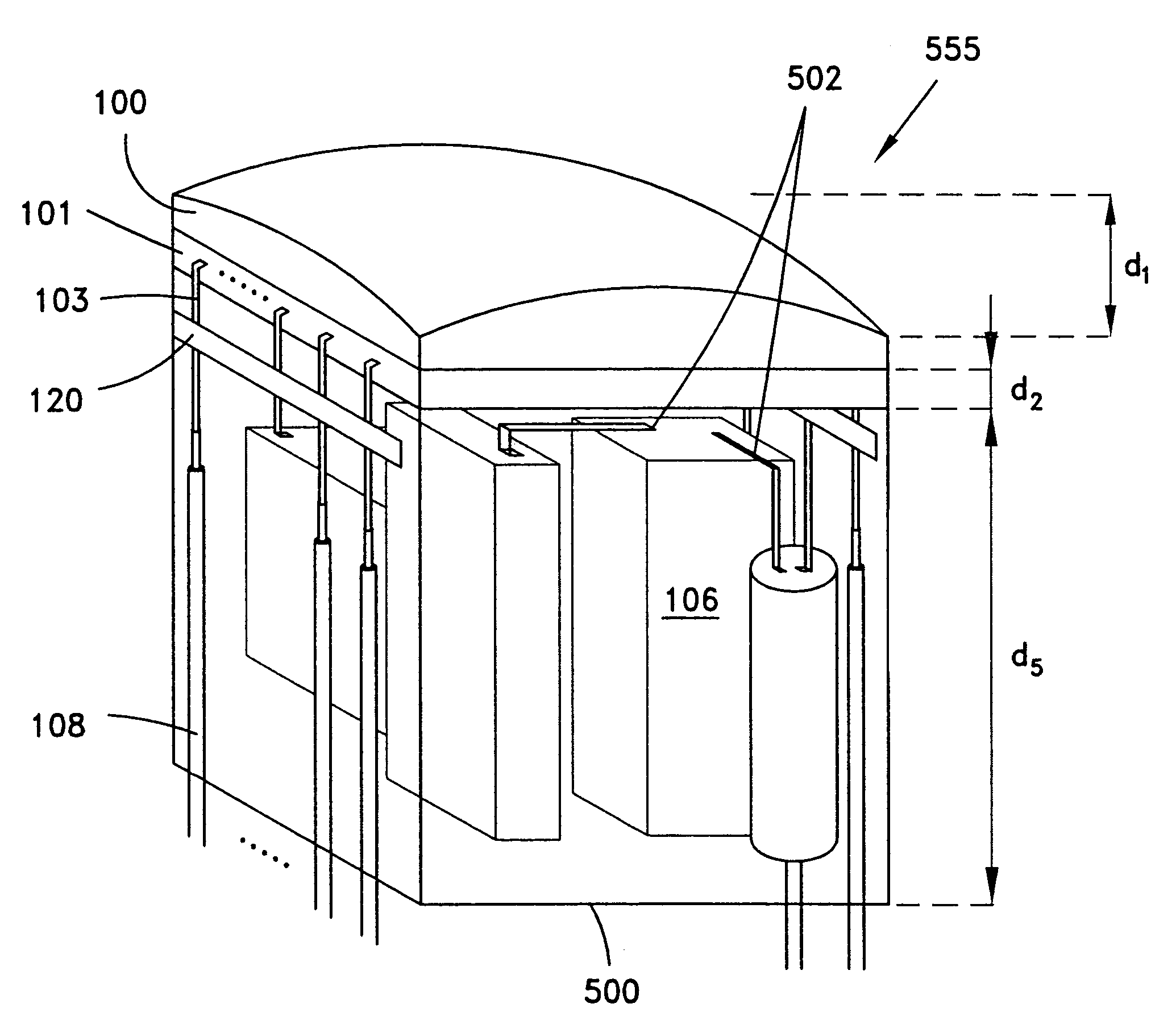
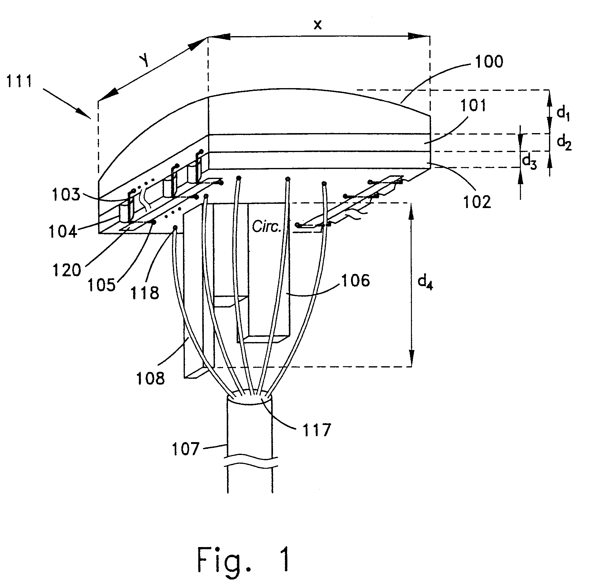
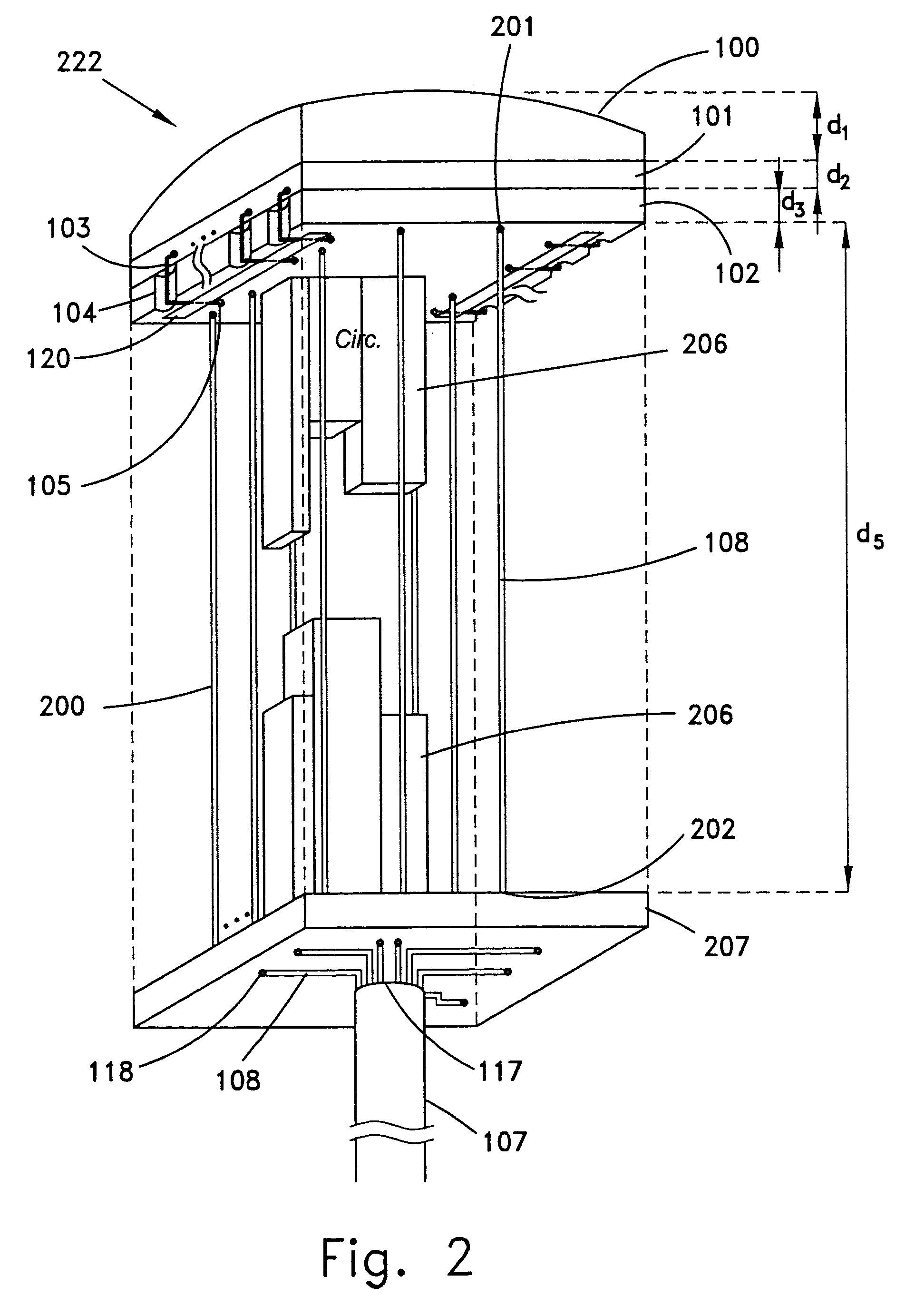
[0060]The present invention provides an autoclavable imager assembly, having minimal size, which functions as a miniature camera head. The camera head of the invention comprises an imaging sensor, such as CCD, to acquire the images and the components required to process and amplify the attained signals and to deliver them via conductive wires to a display system that digitally processes the attained signals. As explained hereinbelow, the quality of the image is greatly dependent on the number of electrical components that are mounted in the vicinity of the imager, to improve the signal quality. Electronic improvement is necessary because the signals that are transmitted via the conductive wires to the display system are distorted and attenuated by electrical noise and because of the presence of various other electrical effects, e.g., electrical resistance, along the conductive wires. The quality of the image also depends on many other factors including, but not limited to: the numbe...


PUM


Abstract

The invention is an imager assembly for a miniature camera head. The assembly comprises an imaging sensor having conductive leads; an objective lens system placed on top of the sensor; circuitry, mounted beneath the imaging sensor, for driving the sensor and amplifying the electrical signals; and conductive wires electrically linking the internal components of the assembly and for linking the assembly to remote locations. The conductive leads are bent and the circuitry and conductive wires are arranged and mounted such that the dimensions in a plane parallel to the sensor plane of the camera head are approximately equal to or less than the dimensions in the plane of the sensor. The circuitry is capable of delivering signals produced by the imaging sensor for further processing and the components of the imager, except for the imaging surface of the sensor and the objective lens system, are encapsulated by an isolating material.

Description

FIELD OF THE INVENTION[0001]The present invention relates to the field of endoscopy and imaging systems used in minimal access therapy and / or diagnostics. More particularly, the invention relates to arrangements of a miniature camera head allowing compact arrangement of the components of the camera head.BACKGROUND OF THE INVENTION[0002]The present invention is directed to imager assemblies for miniature camera heads based on solid state sensors e.g., Charged Couple Device (CCD) sensors. These types of cameras are commonly used in imaging systems in minimal access therapy e.g., minimal access surgery, interventional flexible endoscopy, percutaneous interventional radiology, laparoscopy, etc.[0003]Minimal access therapy and / or diagnostics are generally carried out within body cavities and, therefore, the operating field cannot be directly viewed by the person carrying out the operation. For this reason, the ability to carry out such procedures is dependent on the imaging systems that ...

Claims


Application Information

Patent Timeline
IPC IPC(8): H04N5/225A61B1/04H04N3/14A61B1/05
CPCH04N5/2253A61B1/05H04N2005/2255H04N23/555H04N23/54A61B1/313
Inventor SONNENSCHEIN, ELAZARMALY, BINYAMINZARUD, BORISSHIMSHILASHVILI, PALHAZ
Owner MEDIGUS LTD
Why Eureka
Try Eureka